Appendix i – replacing the sa 8840 controller – Research Concepts RC2500 User Manual
Page 114
RC2500 Antenna Controller
Appendix I
Replacing the SA 8840 107
Research Concepts, Inc. • 5420 Martindale Road • Shawnee, Kansas 66218-9680 • USA
www.researchconcepts.com
Appendix I – Replacing the SA 8840 Controller
It is possible to use the RC2500 to replace the Scientific Atlanta SA8840A Antenna Controller and enjoy
the added capabilities of inclined-orbit tracking and PC remote control. In order to be compatible with the
Antenna and SA8841A outdoor box, resolvers are placed on the azimuth and elevation pivot points, a
potentiometer is installed to sense polarization position (See Appendix H above), and several RC2500
modifications both hardware and software are performed at the factory. The firmware version for this unit
is: version 1.07wsa-p, the date: 2.19.98, and the checksum: 'A1'.
The SA8841A outdoor box reports Limits to the indoor box with open-collector drivers. Six inputs transfer
limit information to the RC2500. They are: AZ_CW, AZ_CCW, EL_UP, EL_DWN, POL_CW, POL_CCW.
The “safe” operating region is defined as the non- conducting state of the drivers. That is a low-voltage
(on the order of 0.4V) on the RC2500 input terminal indicates a limit has been reached. A high voltage
(+24VDC) on the pin indicates that a limit has not been reached. Note that this is different from other
control schemes where the conducting state indicates the safe operating region.
A seventh input, Pedestal_Override, lets the RC2500 know whether the antenna is being jogged under
local control at the base-mounted SA8841 A.I.U. Again, this is an open-collector driver. When Pedestal
override is active, this driver is non-conducting, the input voltage on the pin would be high (+24VDC), and
the RC2500 will indicate “MAINTENANCE” flashing on the lower line of the display.
The drive board of the RC2500, FC-2_5K9135, is modified to accept a “low-side” limit switch input. The
following components are removed: MOV1, MOV2, L1, L2, L3, L4, D2, D3, D4, D5, U3, U4, R3, R7, K3,
D8, R21, and MOV14. Referring to the schematic of the AZ-CCW_LIM input section of the board on
page 101 (Appendix G), resistors R40 and R42 were removed. A single 2K resistor is inserted vertically
into the pad of R40 connected to U10 pin 1. The free end of this resistor is tied via a flying lead to the
+24VDC unregulated supply found at the R21 high-side pad. A jumper is added from the R42 pad
connected to U10 pin 2 to the remaining free pad of R40. Similar modifications are made for the 6
remaining limit input circuits. The Aux relay drive input line are jumpered to free PLD outputs. The table
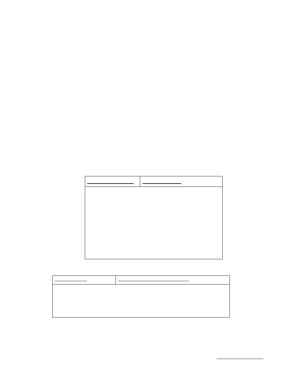
below indicates which RC2500 input connection is used for each outdoor box limit connection.
SA8840A limit signal
RC2500 input pin
AZ Limit Up (CW)
Antenna I/O connector J7 Pin 1
AZ Limit Down (CCW)
Antenna I/O connector J7 Pin 16
EL Limit Up
Antenna I/O connector J7 Pin 15
EL Limit Down
Antenna I/O connector J7 Pin 3
POL Limit Up (CW)
Antenna I/O connector J7 Pin 2
POL Limit Down (CCW)
Antenna I/O connector J7 Pin 14
Pedestal Override
Antenna I/O connector J7 Pin 4
There are four other connections that must be made to disable limit inputs of the RC2500:
RC2500 J7 pin
Disposition for SA8840 version
J7-5 AZ_Fault
Externally jumpered to J7-10 to disable AZ_Fault
J7-18 EL_Fault
Externally jumpered to J7-23 to disable EL_Fault
J6-12 Intest
Externally jumpered to J6-7 (+24VDC supply line)
J6-24 pwr_supply_common
Externally jumpered to J6-21 (+24VDC return line)
The Output of the RC2500 with its 700mA open-collector drivers is directly compatible with the drive
inputs to the outdoor box. The definition of the pins have been changed from that in the original 9135
logic. A new PLD (SA8840) at position U11 on the I/O board has been created to produce the correct
drive logic. A re-cap of the signal tables in section 3.3.2.2 modified for the SA 8840 are shown below.