4 software configuration, 1polarization equipment code, 2reversing the resolver sense direction – Research Concepts RC2500 User Manual
Page 27: Software configuration, Polarization equipment code, Reversing the resolver sense direction
20
RC2500 Antenna Controller
Chapter 3
Installation/Setup
Research Concepts, Inc. • 5420 Martindale Road • Shawnee, Kansas • 66218-9680 • USA
www.researchconcepts.com
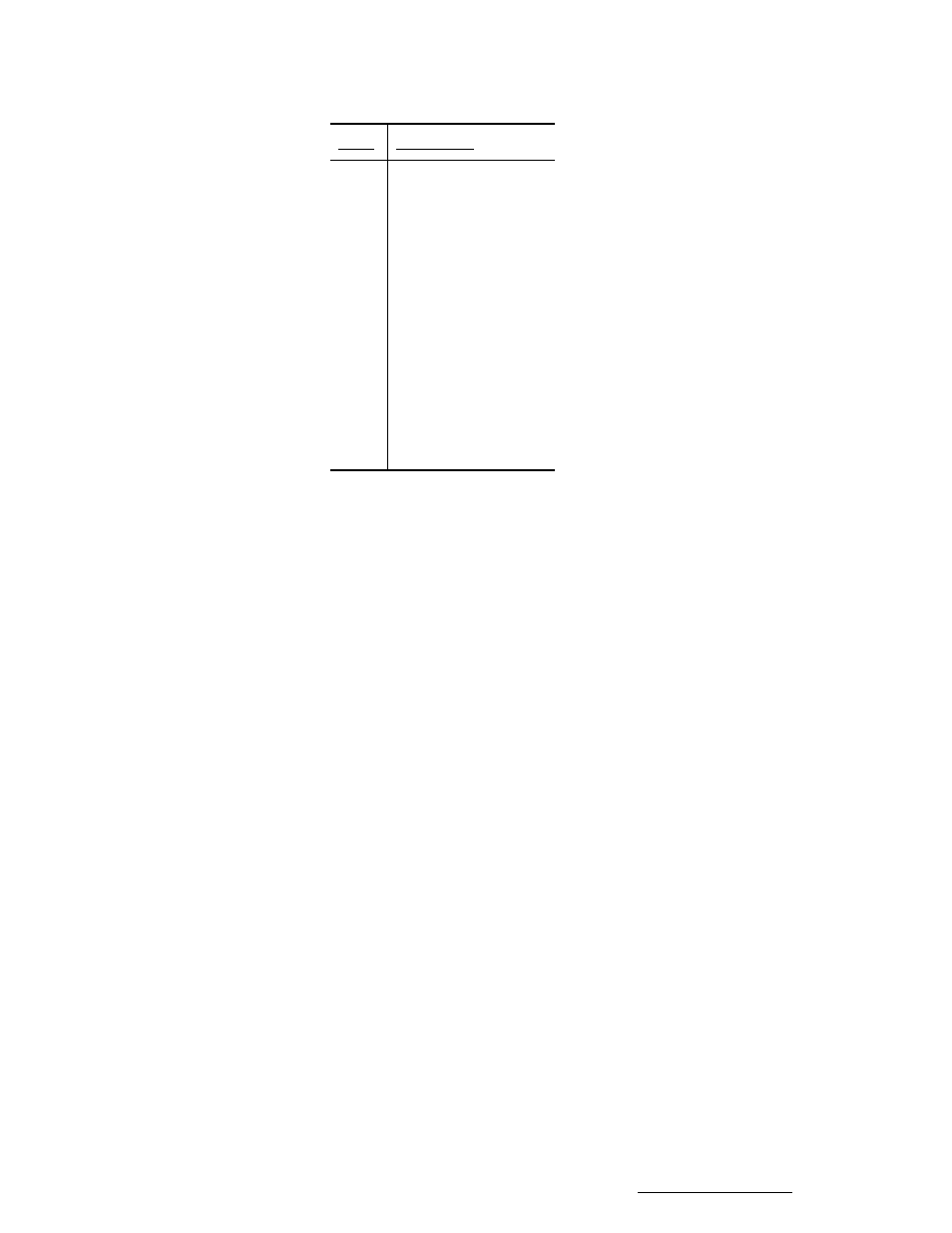
Pin #
Description
1
Nc
2
Nc
3
Receive.
4
Transmit.
5
Nc
6
Transmit return.
7
Nc
8
Nc
9
Receive return.
3.4
Software Configuration
Once the cabling between the RC2500 and the position sensors and the RC2500 and the A.I.U has been
completed, certain configuration items should be set for optimum performance. This section describes
how to set these parameters in the configuration mode of the RC2500. For a discussion of how to enter
CONFIG mode see Chapter 2.
Many of the following items are only visible from CONFIG mode when “Expert Access” has been enabled.
To enable expert access, refer to Section 2.5 and Appendix A.
3.4.1 Polarization Equipment Code
Depending on the application, several different feed configurations may be possible. If the antenna has a
dual-port feed that will simultaneously receive vertical and horizontal polarization signals, only a single
feed position must be stored for each satellite. A single port feed requires that two positions, vertical and
horizontal be stored for each satellite position. If a non-moving feed is in place, or if you are working with
circularly polarized signals, there will be no requirement for positioning of the feed. In this third case
there will be no displayed angle for a polarization axis on the RC2500 display.
Determine your feed type. In CONFIG mode scroll down to the item POL CONTROL EQUIPMENT
CODE. At the prompt, enter 0 for a fixed feed or a circularly polarized feed, enter 1 for a single-port feed,
or enter 2 for a dual port feed.
3.4.2 Reversing the Resolver Sense Direction.
The A.I.U. should already have been wired such that the axes are all moving in the correct direction with
local jog controls if any.
The resolver type position sensors wired as in the table found in the resolver installation section should
result in the sensed position changing in the following manner when the antenna is moved.
• Azimuth CW antenna movement (as viewed by an observer located above the antenna)
must result in an increasing sensed position.
• Elevation UP antenna movement must result in an increasing sensed position.
• When the controller’s POL CW key is depressed, the sensed polarization position must
increase.