Chapter 2 – basic function description, 1 front panel, Front panel – Research Concepts RC2500 User Manual
Page 9
2
RC2500 Antenna Controller
Chapter 2
Basic Function Description
Research Concepts, Inc. • 5420 Martindale Road • Shawnee, Kansas • 66218-9680 • USA
www.researchconcepts.com
Chapter 2 – BASIC FUNCTION DESCRIPTION
This chapter describes the controller's front panel layout, user interface and basic operation. When the
user has completed this chapter, he or she should have a basic understanding of the various operating
modes of the unit, and be able to use the keyboard and liquid crystal display (LCD) to navigate through
those modes.
2.1
Front Panel
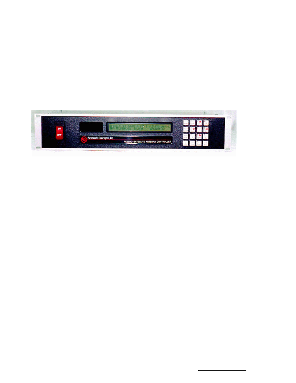
The front panel (Figure 2.1) of the RC2500 contains an ON/OFF switch, a 2 row by 40 column backlit
LCD, and a 4 by 4 matrix keypad with tactile feedback.
Figure 2.1 - RC2500 Front Panel
The field in the upper right hand corner of the LCD is reserved for the display of the current mode of the
controller. The various modes are introduced in the following section. If an error condition is active, an
error message will periodically flash across the bottom row of the display. Error messages are discussed
in chapter 7. Chapter 5 explains the contents of every field on the display for all of the various controller
modes.
An examination of the keyboard in figure 2.2 reveals that many of the keys have 2 or more labels. The
function of each key is determined by the current operational mode of the controller. The various modes
are discussed in the following section.