Research Concepts RC2500 User Manual
Page 138
RC2500 Antenna Controller
Appendix M
Replacing the Harris 7022 131
Research Concepts, Inc. • 5420 Martindale Road • Shawnee, Kansas 66218-9680 • USA
www.researchconcepts.com
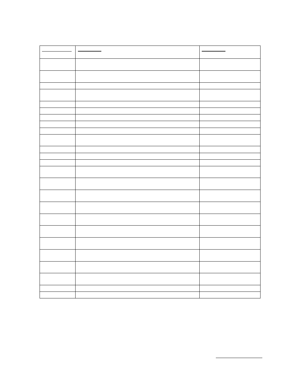
equipment control. A +5 VDC regulated output (200mA max), a +24 VDC unregulated output (1 Amp
max), and an analog voltage input, all referenced to the RC2500 ground, are also available The individual
pin definitions are shown in the table below. Both J6 and J7 are required when operating with the Harris
7022 Antenna Drive (A.I.U.).
RC2500 Pin #
& (resource #)
Description
7022 Pin #
1 (PC3)
Summary Fault dry contact COM, (3A @ 125VAC or 3A
@ 30VDC).
Unused
2 (PC3)
Summary Fault dry contact NO, (3A @ 125VAC or 3A @
30VDC).
Unused
3 (PB1)
Drive Ground (Azimuth CW Limit return).
DRIVE GND TB2-47,48
4 (PB0
HSI.1,P2.4)
Drive Ground (Interlock Status and Az CCW Lim return;
same as J7-17)
DRIVE GND TB2-47,48
5 (PB2)
Drive Ground (Elevation Down Limit return.)
DRIVE GND TB2-47,48
6 (PB3)
Drive Ground (Elevation Up Limit return)
DRIVE GND TB2-47,48
7 (PB5)
Drive Ground (Polarization CW Limit return).
DRIVE GND TB2-47,48
8 (PB4)
Drive Ground (Polarization CCW Limit return).
DRIVE GND TB2-47,48
9
Drive Common (return path, same as J6, pins 2,5,8)
DRIVE GND TB2-47,48
10 (PC0)
PC0 output dry contact NC, (3A @ 125VAC or 3A @
30VDC).
Unused
11 (P0.2)
P0.2 Auxiliary analog/digital input 0 - +5 VDC.
Unused
12
Ground (for digital/analog I/O).
Unused
13
Ground for system bus voltages.
Unused
14 (PC3)
Summary Fault dry contact NC, (3A @ 125VAC or 3A @
30VDC).
Unused
15 (PB1)
Azimuth CW Limit input, 24 VDC low current. (0V = CW
Limit reached)
AZ CW Limit Status
TB2-30
16 (PB0)
Azimuth CCW Limit input, 24VDC (0V = CCW Limit
reached) (same as J7-10 ).
AZ CCW Limit Status
TB2-29
17 (PB2)
Elevation Down Limit input, 24 VDC low current. (0V =
Down Limit reached)
EL Down Limit Status
TB2-28
18 (PB3)
Elevation UP Limit input, 24 VDC low current. (0V = Up
Limit reached)
EL Up Limit Status
TB2-27
19 (PB5)
Polarization CW Limit input, 24 VDC low current. (0V =
CW Limit reached)
POL CW Limit Status
TB2-25
20 (PB4)
Polarization CCW Limit input, 24 VDC low current. (0V =
CCW Limit reached)
POL CCW Limit Status
TB2-26
21 (PC1)
Azimuth Brake, solid state drive, 700mA max sink. (0.4V
= AZ Brake release)
AZ BRAKE TB2-40
22 (PC0)
PC0 output dry contact COM, (3A @ 125VAC or 3A @
30VDC).
Unused
23 (PC0)
PC0 output dry contact NO, (3A @ 125VAC or 3A @
30VDC).
Unused
24
+5 Volts DC digital power, 200mA max.
Unused
25
Unregulated +24 VDC bus voltage, 1 Amp max..
Unused
Once the above connections have been made, verify that antenna motion in the appropriate direction can
be affected from the front panel in MANUAL mode. You may now continue the RC2500 installation with
sections 3.3.3 through 3.5.