3 implementing the tracking algorithms, 1location information, 2antenna radiation pattern – Research Concepts RC2500 User Manual
Page 38: Implementing the tracking algorithms, Location information, Antenna radiation pattern
RC2500 Antenna Controller
Chapter 4
Inclined Orbit Satellites
31
Research Concepts, Inc. • 5420 Martindale Road • Shawnee, Kansas • 66218-9680 • USA
www.researchconcepts.com
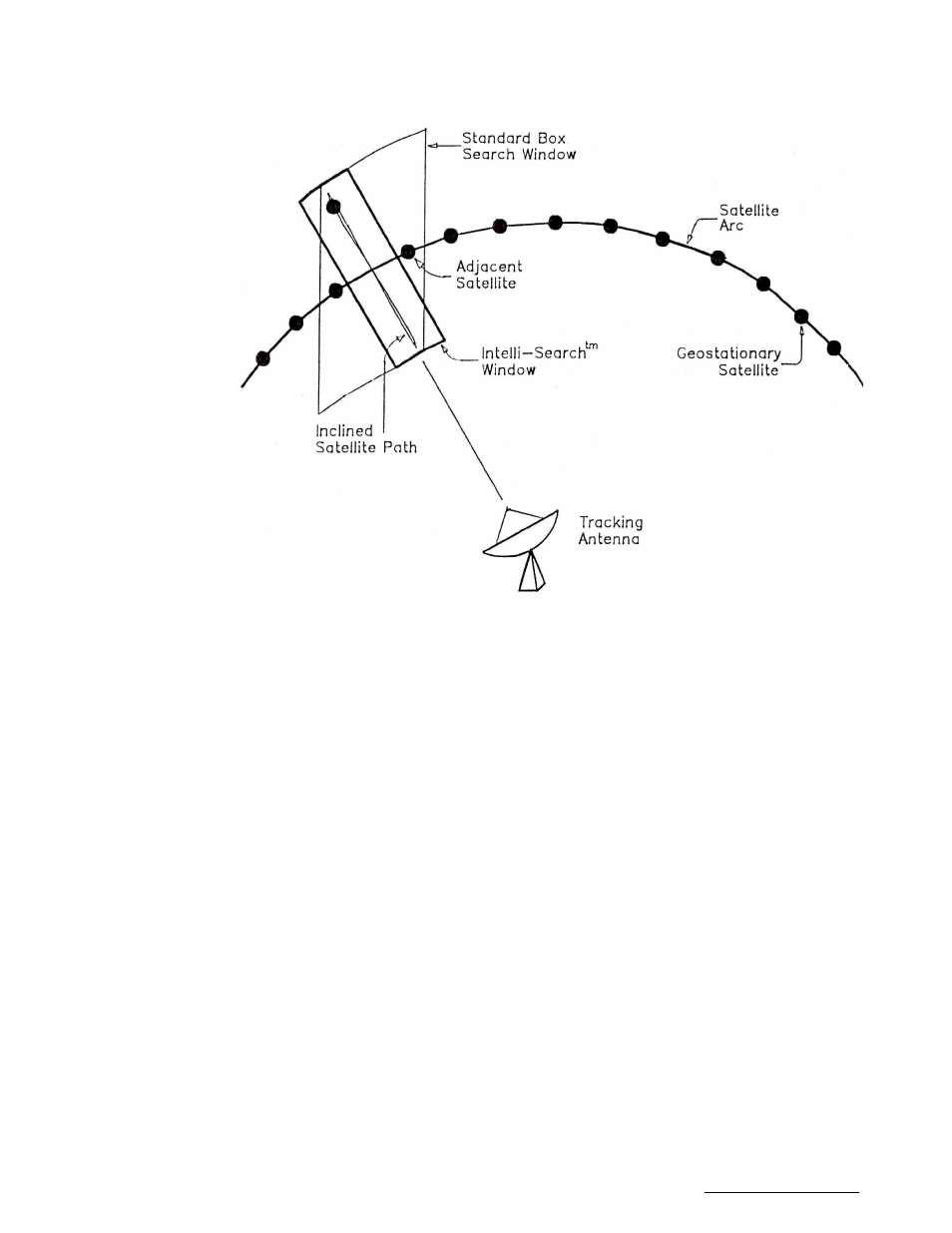
Figure 4.2 - Intelli-Search 4.3
4.3
Implementing the Tracking Algorithms
This section describes the information needed to implement the tracking algorithms. The purpose of this
section is to give the user insights into the operation of the controller and to prepare for the actual entry of
the setup information in the following sections.
4.3.1 Location Information
The Antenna Latitude, Antenna Longitude, and the Longitude of the inclined orbit satellite to be tracked,
must be specified in order to determine the satellite's apparent motion. In most cases the satellite's
apparent motion as seen by the antenna mount is a skewed figure eight shape. This information is
needed to implement the controller's Intelli-Search algorithm.
4.3.2 Antenna Radiation Pattern
The antenna radiation pattern specifies antenna receive power versus antenna pointing angle relative to
boresight. Boresight is the pointing angle associated with maximum received power from a given
satellite. The controller calculates the shape of the antenna's radiation pattern by knowing the Antenna
Size and the frequency Band (C or Ku) currently in use. Antenna Size data is entered via a CONFIG
mode prompt. The frequency Band data is specified in SETUP mode when the user initiates a track on
an inclined orbit satellite. Note that the controller also allows the user to specify a dual band inclined orbit
satellite. For this case the user is prompted to supply frequency band data on entry into TRACK mode,
and is allowed to change the Frequency Band via the TRACK mode menu.
Antenna radiation pattern information is necessary to allow the user to specify a maximum allowable
antenna pointing error (Max Track Error) in decibels (dB) rather than in elevation and azimuth position
counts. The Maximum Track Error is used to determine the step size and the frequency of antenna
movement in the STEP TRACK and PROGRAM TRACK sub-modes. In addition, antenna radiation
pattern information is used in SEARCH mode to determine the width of the parallelogram-shaped search
region, and the angle between successive sweeps.