Antenna i/o connector – Research Concepts RC2500 User Manual
Page 140

RC2500 Antenna Controller
Appendix N
Replacing the NPL 9000 133
Research Concepts, Inc. • 5420 Martindale Road • Shawnee, Kansas 66218-9680 • USA
www.researchconcepts.com
Antenna I/O Connector
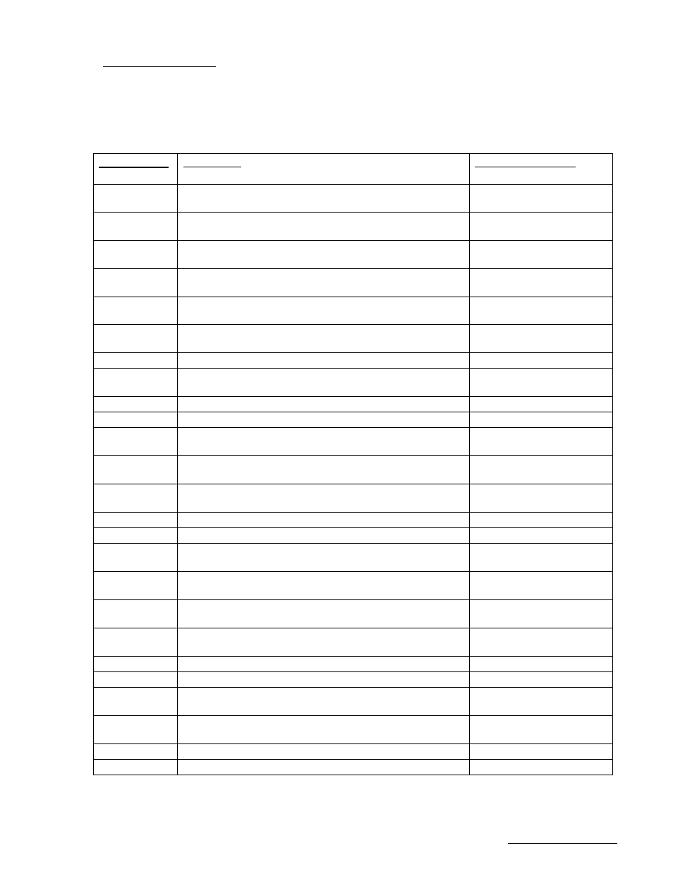
J7, located to the right of J4, is a DB-25 plug identified as the Antenna I/O connector. This connector
acts as the antenna motion control port of the RC2500. The port consists of 9 solid-state low-side relay
drivers rated at 700mA sink each. Max voltage is +27VDC on these drivers. Current is returned to the
A.D.U. via the Drive Common line (pins 2,5, and 8). In addition to the drivers, this port supports three 24
VDC, low current, status inputs with isolated returns. The individual pin definitions as well as their mating
connection at the NPL 9000 Antenna Drive Unit are shown in the table below.
RC2500 Pin #
& (resource #)
Description
NPL9000 ADU Pin #
1 (PA1)
Azimuth Drive East, pull-down drive, 700mA max sink.
(0.4V = move east)
AZ EAST - TB1-4
2
Drive Common (return path for AZ, EL, & POL drive
command lines)
No connect
3 (PA0)
Azimuth Drive West, pull-down drive, 700mA max sink.
(0.4V = AZ move west)
AZ WEST - TB1-2
4 (PA4)
Elevation Drive Up, pull-down drive, 700mA max sink.
(0.4V = EL move up)
EL UP TB1-8
5
Drive Common (return path for AZ, EL, & POL drive
command lines)
No connect
6 (PA3)
Polarization CCW Command, pull-down drive, 700mA
max sink. (0.4V = Pol move CCW)
POL CCW - TB1-16
7 (PA7)
unused output
No connect
8
Drive Common (return path for AZ, EL, & POL drive
command lines)
No connect
9 (PA6)
unused output
No connect
10 (PB0)
unused input
No connect
11 +12V src
+12V Reg. Source for AZ West and AZ East
AZ West +; TB1-1 AZ
East +; TB1-3
12 +12V src
+12V Reg. Source for EL Up and EL Down
EL UP +; TB1-7 EL
DOWN +; TB1-9
13 +12V src
+12V Reg. Source for POL CW and POL CCW
POL CW +; TB1-13
POL CCW +; TB1-15
14 (P2.4)
unused input
No connect
15 (HSI.1)
unused input
No connect
16 (PB7)
Local Jog Control Active sense return line (return path for
signal)
TB1-20
17 (PB0,
HSI.1,P2.4)
unused input return; (same as J6-4)
No connect
18 (PB0
HSI.1,P2.4)
unused input return; (same as J6-4)
No connect
19 (PB7)
Local Jog Control Active sense input (return path for
signal)
TB1-19
20
nc
No connect
21 (PA2)
unused output
No connect
22 (PA5)
Elevation Drive Down, pull-down drive, 700mA max sink.
(0.4V = EL move up)
EL DOWN - TB1-10
23 (PC2)
Polarization CW Command, pull-down drive, 700mA max
sink. (0.4V = move CW)
POL CW - TB1-14
24 (PB6)
unused input (dedicated pin….Do Not Use)
dedicated pin, do not use.
25 (PB6)
unused input return
No connect