Rose Electronics QuadraVista II User Manual
Page 12
6
QUADRAVISTA 2 INSTALLATION AND OPERATIONS MANUAL
Installing the Computers
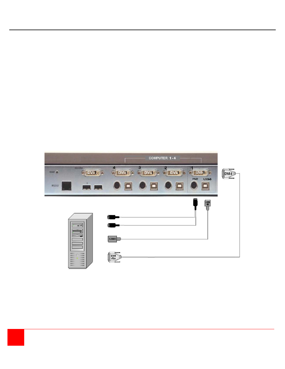
Connect up to four computers to the corresponding video (DVI-I), keyboard and mouse ports on the QuadraVista 2
as shown below. It is recommended that the computers being connected and QuadraVista 2 be powered off until all
cable connections have been made.
Connect a computer's video output port (DVI or VGA) to the QuadraVista 2's DVI-I connector for computer #1. If a
VGA (HD15F) connector is on the computer, a VGA to DVI cable must be used. Next connect a USB cable from the
computer's keyboard/mouse USB port to the QuadraVista 2's USB input port. If the keyboard and mouse ports on
the computer are PS/2, use a PS/2 "Y" cable to connect from the computer's keyboard and mouse PS/2 ports to the
PS/2 keyboard/mouse input port on the QuadraVista 2.
Connect computer #2, #3, and #4 to the corresponding connectors on the QuadraVista 2's rear panel. You are not
limited in using the CPU ports to connect to a computer. The CPU port can also be connected to a Rose KVM
switch’s KVM port. This can provide access to as many as 1,000 computers or servers. The DVI video input can
accept any analog or digital video signal from devices like surveillance cameras, a DVD player, or other compatible
video sources and display it on your KVM monitor.
When all cable connections have been made, turn the power on to the QuadraVista 2 and the computers. All six
front panel LEDs will flash momentarily, then the green QUAD led will light indicating that the unit is ready for
operation and the user monitor will display in the Quad mode, showing all four computers video. If only two video
sources are connected, quadrant 3 and 4 will be blank.
Figure 4. Video source installation
PS/2 “Y” cable
Or
USB cable (A / B)
DVI to DVI
Or
VGA to DVI cable