1 reaction times for the ax51xx, 2 reaction times for the ax52xx – BECKHOFF AX5805 Installation User Manual
Page 15
Product description
AX5805
13
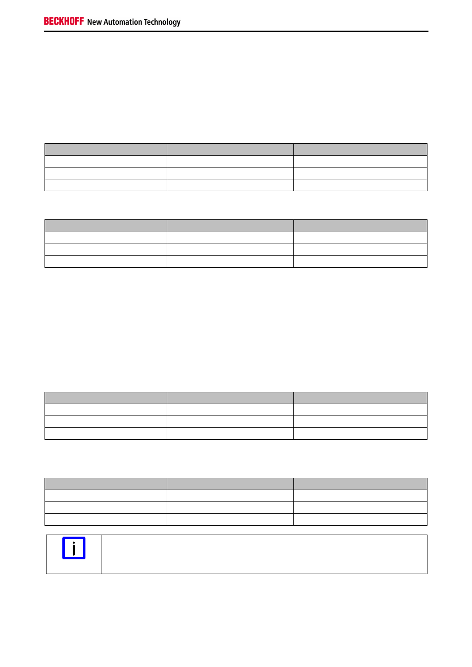
3.3.1 Reaction times for the AX51xx
The reaction time is the amount of time from a safety-related event is received (as an input signal to the
AX5805) until the internal circuits are switched off. If the TwinSAFE communication is to be included in the
calculation, the watchdog time of the TwinSAFE connection must be added to this. For a worst-case
consideration, the maximum time with update of the CoE data must always be used.
Firmware
≤
04
Operation mode
Minimum reaction time
Maximum reaction time
STO-MODE
18ms
36ms
Default process data
22ms
44ms
Extended process data
23ms
46ms
Firmware > 04 (Revision number
≥
AX5805-0000-0017)
Operation mode
Minimum reaction time
Maximum reaction time
STO-MODE
15ms
30ms
Default process data
34ms
68ms
Extended process data
34ms
68ms
3.3.2 Reaction times for the AX52xx
The reaction time is the amount of time from a safety-related event is received (as an input signal to the
AX5805) until the internal circuits are switched off. If the TwinSAFE communication is to be included in the
calculation, the watchdog time of the TwinSAFE connection must be added to this. For a worst-case
consideration, the maximum time with update of the CoE data must always be used.
Firmware
≤
04
Operation mode
Minimum reaction time
Maximum reaction time
STO-MODE
39ms
78ms
Default process data
47ms
94ms
Extended process data
48ms
96ms
Firmware > 04 (Revision number
≥
AX5805-0000-0017)
Operation mode
Minimum reaction time
Maximum reaction time
STO-MODE
15ms
30ms
Default process data
34ms
68ms
Extended process data
34ms
68ms
Note
STO mode reaction times
The reaction times for the STO mode are only valid, when both axis are configured for the
STO mode.