Comtech EF Data CDS-100 User Manual
Page 103
CDS-100 Diversity Switch
MN-CDS100
Cables and Connections
Revision 1
5–47
5.9.2
Modem-to-User Data Interface Kit and Connection Examples
In addition to the Modem-to-Switch control cabling shown previously, a number of data
interface configuration kits are available for use with the CDM-710 Broadcast Satellite Modem.
Separate cabling kits are needed for these data interfaces.
While different data interface cards may be installed into both Interface slots, only
one data interface type is operable at a given time. The data interface
combinations allowable in the CDM-710 chassis Interface Slots 1 and 2 are as
follows:
Interface Slot 1
Interface Slot 2
ASI (CDI-40)
None
HSSI (CDI-60)
None
None
GigE (CDI-70)
5.9.2.1 Non-IP Modem-to-User Data Interface Kit and Connection
Examples
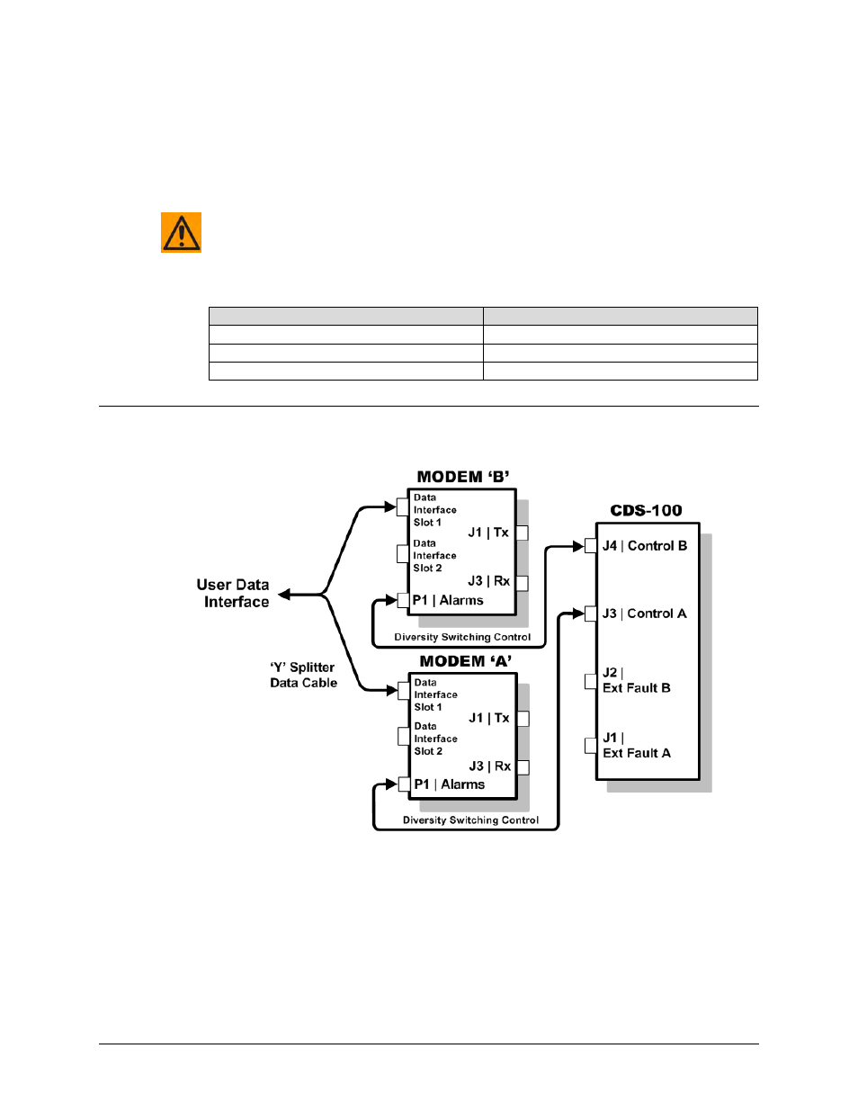
Figure 5-39. CDM-710 Block Diagram – UserModemSwitch
Figure 5-39 shows the block diagram typical for the kits shown in Sects. 5.9.2.1.1 and 5.9.2.1.2.
For example, Sect. 5.9.2.1.1 identifies the interface kit used with the CDI-40 ASI 75Ω data
interface.
With the exception of the CDI-70 Gigabit Ethernet data interface configuration shown in Sect.
5.9.2.2, which uses user-provided Ethernet cables and Layer 2 Switch, you must use one
interface kit per modem pair for each interface (see examples for specific quantities).