Figure 5-22 – Comtech EF Data CDS-100 User Manual
Page 84
CDS-100 Diversity Switch
MN-CDS100
Cables and Connections
Revision 1
5–28
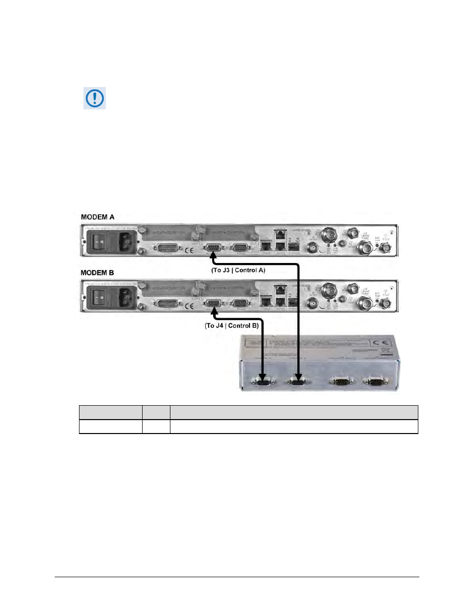
5.6.1
CDS-100 CDM-760, CDM-750 Control Interface Cabling Using Kit
KT-0000265
1)
Excluding modems, the KT-0000265 CDS-100 Diversity Switch Kit (Sect. 5.2.1)
provides all components shown in Figure 5-22.
2)
When you connect the Control Interface cables between the CDS-100 and the
modems, make sure that you securely fasten the screw locks on the Type ‘D’
connectors. This prevents accidental disconnection of the cables, particularly
when you are removing and replacing a backup unit.
3)
Terrestrial data interface components/kits must be ordered separately. See
Sect. 5.6.2 for CDM-760/-750 terrestrial data interface configuration and
connection examples and details.
CEFD Part No.
Qty
Description
CA/WR9378-4
2
Control Cable – Universal, DB-9M, 4’
Figure 5-22. CDM-760/-750 Modem-to-Switch Control Connections (CEFD Kit KT-
0000265)