Comtech EF Data CDS-100 User Manual
Page 63
CDS-100 Diversity Switch
MN-CDS100
Cables and Connections
Revision 1
5–7
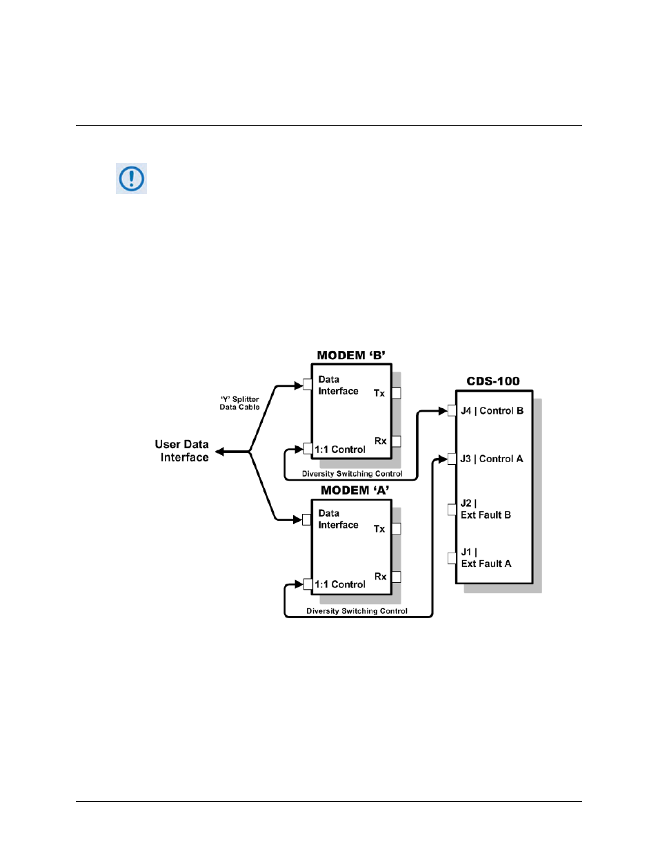
5.3.2
Modem-to-User Data Interface Connections and Examples
5.3.2.1 Modem-to-User Non-IP Data Interface Connections and Examples
The data cables and components identified in each of the examples that follow in
this section must be purchased separately, as required.
In addition to the control Modem-to-Switch control cabling shown previously, a number of data
interface configurations are available for the CDM-625A and CDM-625 Advanced Satellite
Modems. The Figure 5-2 block diagram is typical for the examples shown in Sects. 5.3.2.1.1
through 5.3.2.1.8.
With the exception of the IP (10/100 Ethernet) Interface configurations shown in Sect. 5.3.2.2
(which use customer-supplied Ethernet cables and Layer 2 switches), you must use one cabling
and component kit per modem pair for each user interface (see examples for specific
quantities).
Figure 5-2. CDM-625/A Block Diagram – UserModemSwitch