Comtech EF Data CDS-100 User Manual
Page 109
CDS-100 Diversity Switch
MN-CDS100
Cables and Connections
Revision 1
5–53
5.10.2 Modem-to-User Data Interface Kit and Connection Examples
In addition to the Modem-to-Switch control cabling shown previously, a number of data
interface configuration kits are available for use with the CDM-700 Satellite Modem. Separate
cabling kits are needed for these data interfaces.
The data interface combinations allowable in the CDM-700 chassis Interface Slots
1 and 2 are as follows:
Interface Slot 1
Interface Slot 2
Dual G.703 (CDI-10)
None
Dual G.703 (CDI-10)
HSSI (CDI-60)
GigE (CDI-70)
OC3 Optical (CDI-50-1) Single Mode
None
155MB Copper (CDI-50-1)
HSSI (CDI-60)
None
HSSI (CDI-60
GigE (CDI-70)
GigE (CDI-70)
None
GigE (CDI-70)
None
Dual G.703 (CDI-10)
HSSI (CDI-60)
GigE (CDI-70)
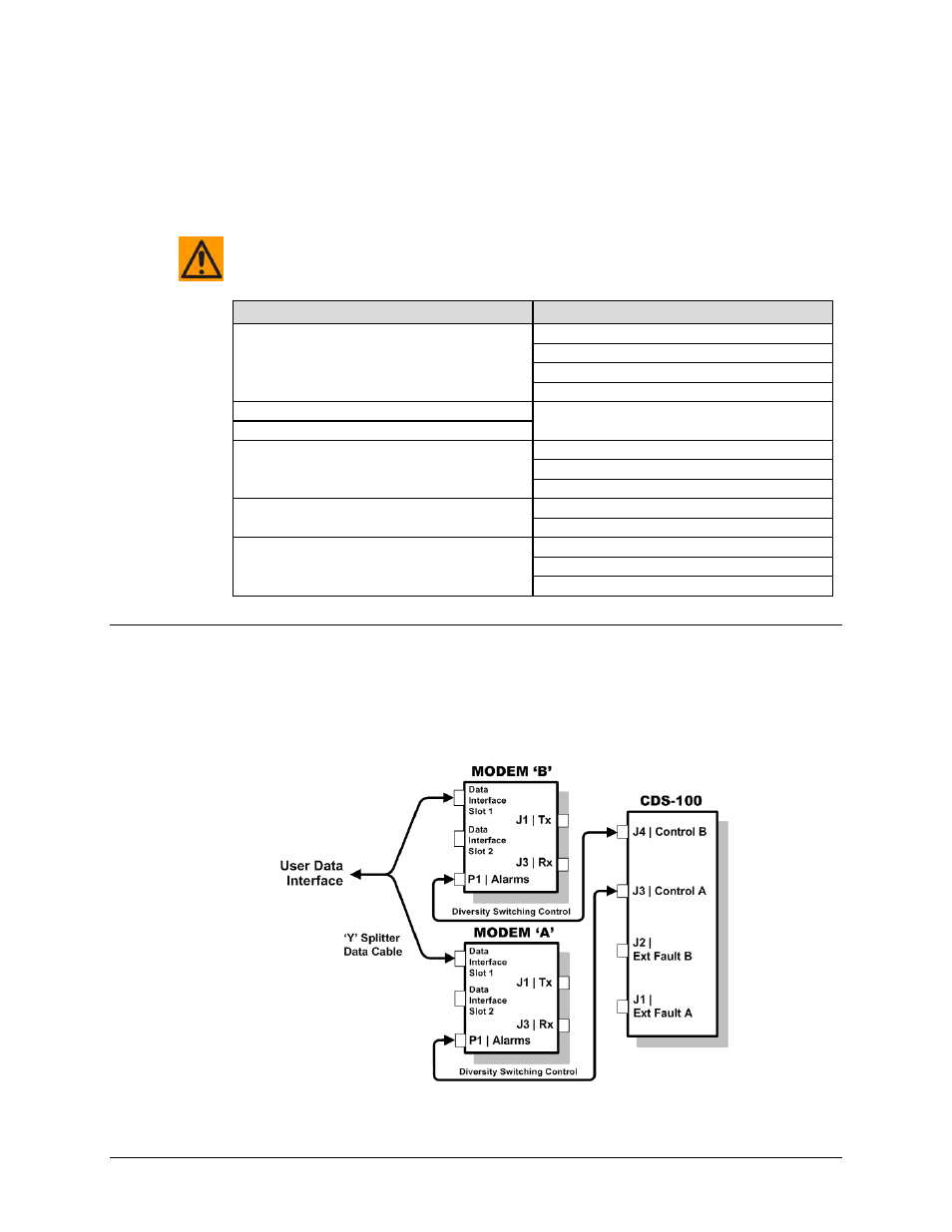
5.10.2.1 Non-IP Modem-to-User Data Interface Kit and Connection
Examples
Figure 5-44 shows the block diagram typical for the kits shown in Sects. 5.10.2.1.1 through
5.10.2.1.3. For example, Sect. 5.10.2.1.1 identifies the interface kit used with the CDI-10 Dual
G.703 E3/T3/STS-1 and CDI-60 HSSI data interfaces.
Figure 5-44. CDM-700 Block Diagram – UserModemSwitch