2 cds-100 configure side features, 1 ground stud – Comtech EF Data CDS-100 User Manual
Page 39
CDS-100 Diversity Switch
MN-CDS100
Switch Connectors and Pinouts
Revision 1
3–7
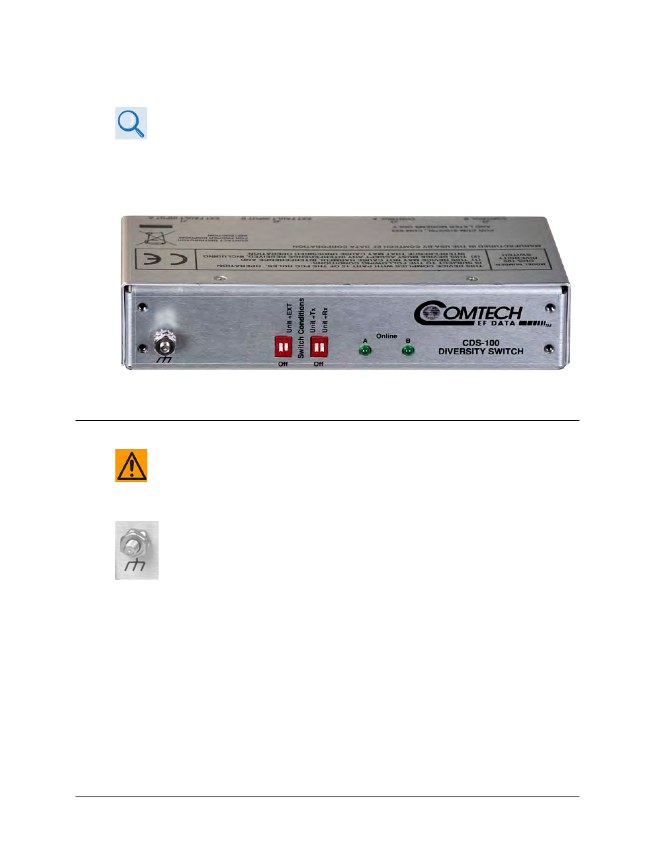
3.2.2 CDS-100 Configure Side Features
•
See Sect. 1.3.1 in Chapter 1. INTRODUCTION for information about the LED
Indicators.
•
See Sect. 1.3.1 in Chapter 1. INTRODUCTION and Sect. 4.9 in Chapter 4. MODEM
AND
SWITCH CONFIGURATION for information about the “Switch Conditions”
DIP Switches.
Figure 3-4. CDS-100 – Configure Side Features
3.2.2.1 Ground Stud
CAUTION – PROPER GROUNDING PROTECTION IS REQUIRED. THE INSTALLATION
INSTRUCTIONS REQUIRE THAT YOU MUST ENSURE THE INTEGRITY OF THE
PROTECTIVE EARTH AND THAT YOU MUST MAINTAIN THE EQUIPMENT’S
CONNECTION TO THE PROTECTIVE EARTH AT ALL TIMES.
Use the #10-32 stud provided on the Configure Side of the Switch for connecting a
common chassis ground among equipment.