Comtech EF Data CDS-100 User Manual
Page 71
Advertising
CDS-100 Diversity Switch
MN-CDS100
Cables and Connections
Revision 1
5–15
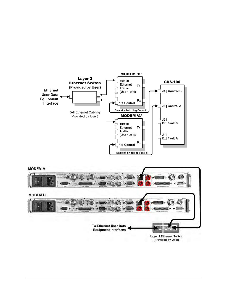
5.3.2.2.3 Router Mode (Optional IP Packet Processor Required)
Figure 5-13 shows the block diagram and cabling example for a CDM-625/A diversity switching
configuration using the IP (10/100 Ethernet) Interface in Router Mode, with the optional IP
Packet Processor installed and enabled.
This configuration requires no cabling kit – you must use user-provided Ethernet cables and
Layer 2 switch for direct connection to the modem via only one of four RJ-45 ports.
CDM-625/A Block Diagram – 10/100 Ethernet Router Mode
Figure 5-13. CDM-625/A 10/100 Ethernet Interface Example – Router Mode
Advertising
See also other documents in the category Comtech EF Data Equipment:
- CDD-880 (124 pages)
- CDM-800 (130 pages)
- ODMR-840 (184 pages)
- CDM-750 (302 pages)
- CDM-840 (244 pages)
- SLM-5650A (420 pages)
- CTOG-250 (236 pages)
- CDM-700 (256 pages)
- CDM-760 (416 pages)
- CDM-710G (246 pages)
- CDM-600/600L (278 pages)
- CDMR-570L (512 pages)
- CDM-625 (684 pages)
- CDM-625A (756 pages)
- CDD-564A (240 pages)
- CDD-564L (254 pages)
- CLO-10 (134 pages)
- MCED-100 (96 pages)
- CDMR-570AL (618 pages)
- CDM-600 LDPC (2 pages)
- BUC Power Supply Ground Cable (2 pages)
- MPP70 Hardware Kit for CDM-570L (4 pages)
- MPP50 Hardware Kit for CDM-570L (4 pages)
- CDM-625 DC-AC Conversion (4 pages)
- CDM-625 DC-AC Conversion with IP Packet Processor (4 pages)
- DMDVR20 LBST Rev 1.1 (117 pages)
- DMD-2050 (342 pages)
- DMD2050E (212 pages)
- DMD1050 (188 pages)
- OM20 (220 pages)
- QAM256 (87 pages)
- DD240XR Rev Е (121 pages)
- MM200 ASI Field (5 pages)
- DM240-DVB (196 pages)
- MM200 (192 pages)
- CRS-150 (78 pages)
- CRS-280L (64 pages)
- CRS-170A (172 pages)
- CRS-180 (136 pages)
- SMS-301 (124 pages)
- CiM-25/8000 (186 pages)
- CiM-25 (26 pages)
- CRS-500 (218 pages)
- CRS-311 (196 pages)
- CIC-20 LVDS to HSSI (26 pages)