Comtech EF Data CDS-100 User Manual
Page 37
CDS-100 Diversity Switch
MN-CDS100
Switch Connectors and Pinouts
Revision 1
3–5
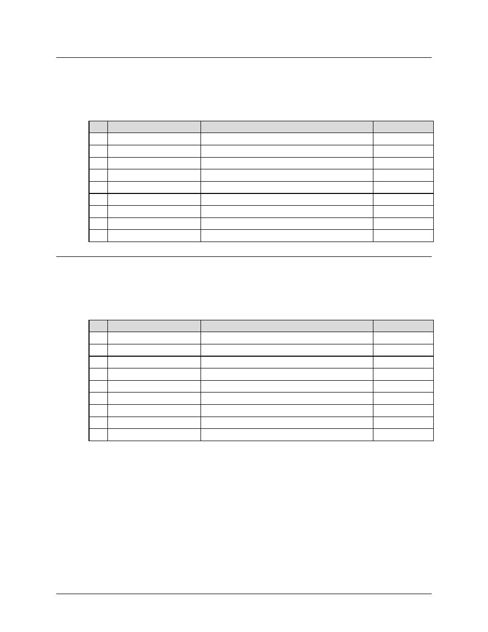
3.2.1.1 ‘J1 | Ext Fault Input A’ Control Connector (DB-9M, Modem ‘A’)
The ‘J2 | Ext(ernal) Fault Input A’ control connector is a 9-pin Type ‘D’ male interface. Pins 2, 4,
and 5 provide optional electrical types for connection to customer supplied external equipment.
Table 3-1. ‘J1 | Ext Fault Modem A’ Control Connector Pin Assignments
Pin Signal Name
Signal Function
Type
1 +5V
+5 VDC output signal, current limited to 2.5 mA
Output
6
Ground
Ground
Passive
2 Control #3 – Active High
Voltage Range +5V to +15V
Input
7
---
Should not be used
No Connect
3 ---
Should not be used
No Connect
8
Ground
Ground
Passive
4 Control #2 – Active Low
CMOS logic “0” or Relay closure to ground
Input
9
---
Should not be used
No Connect
5 Control #1 – Active Low
CMOS logic “0” or Relay closure to ground
Input
3.2.1.2 ‘J2 | Ext Fault Input B’ Control Connector (DB-9M, Modem ‘B’)
The ‘J2 | Ext(ernal) Fault Input B’ control connector is a 9-pin Type ‘D’ male interface. Pins 2, 4, and
5 provide optional electrical types for connection to customer supplied external equipment.
Table 3-2. ‘J2 | Ext Fault Modem B’ Control Connector Pin Assignments
Pin Signal Name
Signal Function
Type
1 +5V
+5 VDC output signal, current limited to 2.5 mA
Output
6
Ground
Ground
Passive
2 Control #3 – Active High
Voltage Range +5V to +15V
Input
7
---
Should not be used
No Connect
3 ---
Should not be used
No Connect
8
Ground
Ground
Passive
4 Control #2 – Active Low
CMOS logic “0” or Relay closure to ground
Input
9
---
Should not be used
No Connect
5 Control #1 – Active Low
CMOS logic “0” or Relay closure to ground
Input