Figure 5-19 – Comtech EF Data CDS-100 User Manual
Page 80
CDS-100 Diversity Switch
MN-CDS100
Cables and Connections
Revision 1
5–24
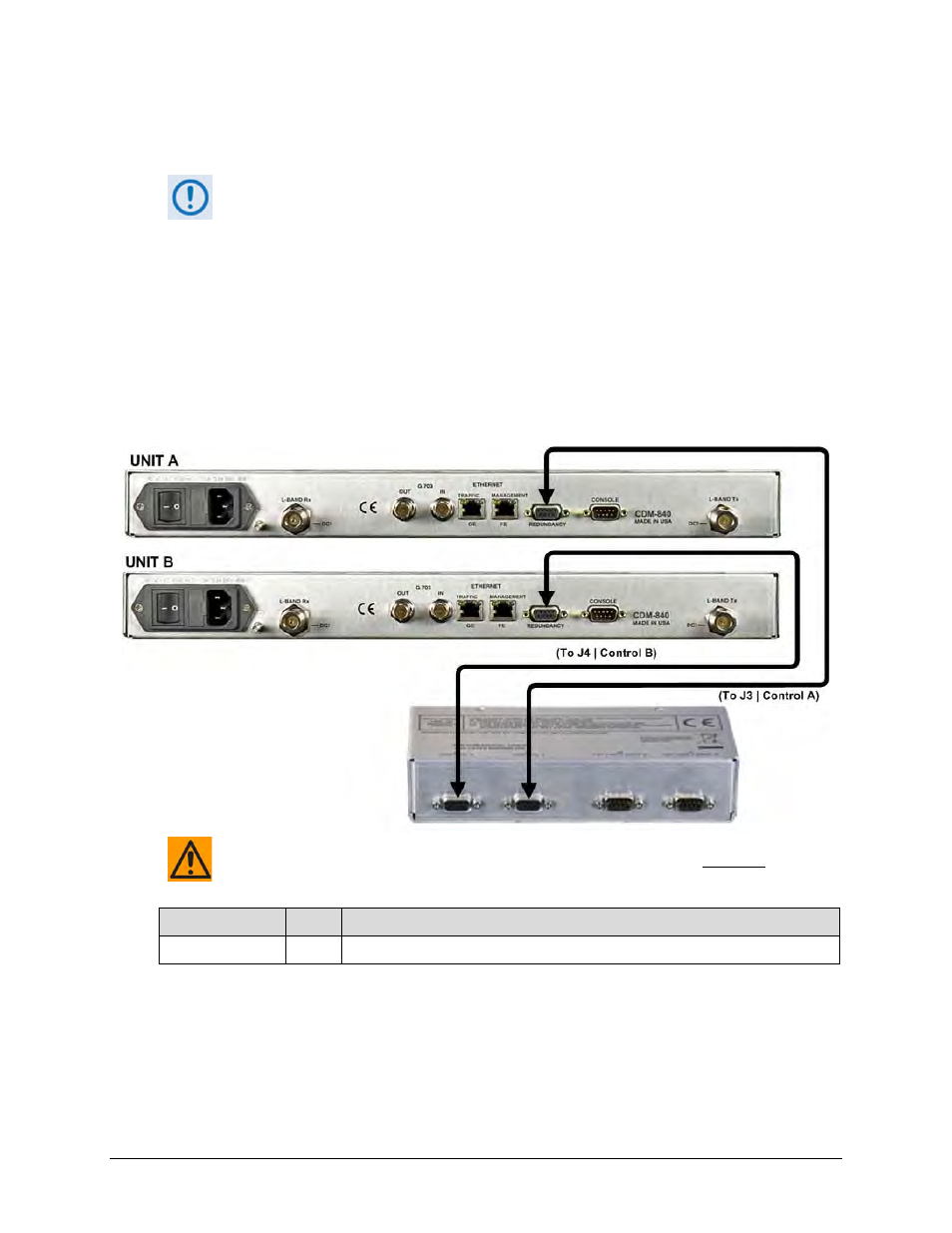
5.5.1
CDS-100CDM-840 Control Interface Cabling Using Kit
KT-0000265
1)
Excluding modems, the KT-0000265 CDS-100 Diversity Switch Kit (see Sect.
5.2.1) provides all components shown in Figure 5-19.
2)
When you connect the Control Interface cables between the CDS-100 and the
CDM-840s, make sure that you securely fasten the screw locks on the Type ‘D’
connectors. This prevents accidental disconnection of the cables, particularly
when you are removing and replacing a backup unit.
3)
Terrestrial data interface cables, components or kits must be purchased
separately. See Sect. 5.5.2 for the terrestrial data interface configuration and
connection examples and details.
CAUTION – It is ESSENTIAL that you make the control connections correctly.
CEFD Part No.
Qty
Description
CA/WR9378-4
2
Control Cable – Universal, DB-9M, 4’
Figure 5-19. CDM-840 Unit-to-Switch Control Connections (CEFD Kit KT-0000265)