Comtech EF Data CDS-100 User Manual
Page 26
CDS-100 Diversity Switch
MN-CDS100
Introduction
Revision 1
1–6
500ms. Note that constant signal level may also be applied. See Table 1-2 for the definition of
each pin assignment.
Table 1-2. CDS-100 – Ext Fault Connector Pin Definition
Pin Signal Name
Signal Function
Type
1 +5V
+5 VDC output signal, current limited to 2.5 mA
Output
6 Ground
Ground
Passive
2 Control #3 – Active High
Voltage Range +5V to +15V
Input
7 ---
Should not be used
No Connect
3 ---
Should not be used
No Connect
8 Ground
Ground
Passive
4 Control #2 – Active Low
CMOS logic “0” or Relay closure to ground
Input
9 ---
Should not be used
No Connect
5 Control #1 – Active Low
CMOS logic “0” or Relay closure to ground
Input
Chapter 3. CONNECTORS
AND
PINOUTS
You may enable Manual Switching via the Online modem, through its front panel or by remote
control.
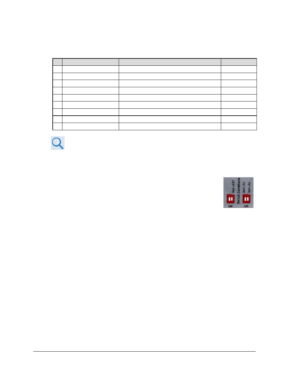
You may control Automatic Switching via setup of the desired switch-over
conditions using the DIP switches on the CDS-100. This selection provides a
great deal of flexibility in the operation of the switch: you can select between
Modem Unit faults only; Modem Unit faults or Receive Traffic faults; Modem
Unit faults or Transmit Traffic faults; Modem Unit faults or External Control; or
all three.
Automatic Switching is assisted by the two green LEDs, located to the right of the DIP switches
on the Configuration Side of the CDS-100, indicating which modem is Online.
With the ‘bridging’ architecture of the CDS-100 (whereby identical terrestrial data traffic signals
are routed to both Online and Offline modems), the diversity controller can avoid unnecessary
switchovers. By examining the fault status of both modems, it can infer if the fault is external to
the system.
For example, you have configured your CDS-100 for switchover following Unit faults or Transmit
Traffic faults, and you have configured your modems for external clock operation. Now, suppose
that the external equipment (network, multiplex, router, etc.) fails – both the Offline and Online
modems will now show a Transmit Traffic fault (No Clock Detected from Terrestrial Port). The
CDS-100 Controller State Machine will see that both faults have occurred at the same time (in
fact, within a 0.5 second window), and infers that the fault is external. Therefore, no
unnecessary switchover is initiated.