Comtech EF Data CDS-100 User Manual
Page 91
CDS-100 Diversity Switch
MN-CDS100
Cables and Connections
Revision 1
5–35
5.7.2
Modem-to-User Data Interface Connections and Examples
The data cables and components identified in each of the examples that follow in
this section must be purchased separately, as required.
In addition to the Modem-to-Switch control cabling shown previously, a number of data
interface configurations are available for the CDM-570/A and CDM-570L/AL Satellite Modems.
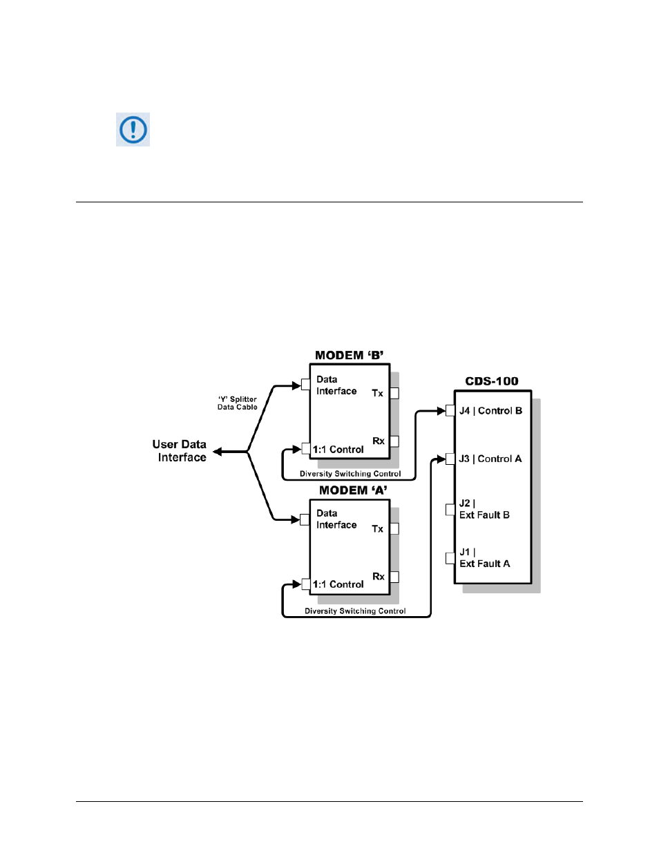
5.7.2.1 Non-IP Modem-to-User Data Interface Connections and Examples
The block diagram shown in Figure 5-28 is typical for the examples shown in Sects. 5.7.2.1.1
through 5.7.2.1.3.
With the exception of the CDM-570/L ONLY IP (10/100 Ethernet) Interface configuration shown
in Sect. 5.7.2.2, where you must use user-provided Ethernet cables and hub, you will need one
cable and component set per modem pair for each user interface (see examples for specific
quantities).
Figure 5-28. CDM-570/A, CDM-570L/AL Block Diagram – UserModemSwitch