2 wiring, sensor, 3 wiring, 4-20 ma outputs, 2 wiring, sensor 2.2.3 wiring, 4-20 ma outputs – Electro-Chemical Devices (ECD) T80 User Manual
Page 20
provide a good seal to the cable. The instrument can be powered up at this point with no harm to the analyzer
but it is best to wait until the sensor is installed.
24VDC (4 wire configuration)
Attach the 24VDC power cable to terminals #1 and #2 as shown in Figure 2.2.2 and on the diagram inside of the
T80 cover. Attach the 4-20 mA1 cable to terminals #3 (out) and #2 (return)single channel unit and attach the 4-
20 mA2 cable to terminals #4 (out) and #2 (return) for a two channel instrument. Feed the cables through the
gland fitting on the right hand side of the T80. Tighten the cable gland to provide a good seal to the cable. The
instrument can be powered up at this point with no harm to the analyzer but it is best to wait until the sensor is
installed.
110/220 VAC (4 wire configuration)
Attach power cable as shown in Figure 2.2.2 or as on the diagram inside of the T80 cover. Feed the cable
through the gland fitting on the right hand side of the T80. Tighten the cable gland to provide a good seal to the
cable. The instrument can be powered up at this point with no harm to the analyzer but it is best to wait until
the sensor is installed.
2.2.2
W
IRING
,
S
ENSOR
Attach the sensor wires as described on the diagram inside the T80 cover. Feed the sensor cable through the
gland fitting on the left hand side of the T80. Do not use the same gland fitting for the AC power or
Alarm/Relays. The green terminal strip connectors are detachable from the circuit boards. Remove the
connector by pulling straight back from the circuit board.
2.2.3
W
IRING
,
4-20
M
A
O
UTPUTS
Loop Powered Instruments:
Connect the 4-20 mA cable to terminals #1 (+24V) and #2 (-24V), Model T80-XX-0 X-XX.
24 VDC or 110/220 VAC powered instruments:
For instruments powered with 24VDC or the internal power supply, Model T80-XX-1X-XX (24VDC) and T80-XX-
2X-XX (110/220 VAC), connect the 4-20 mA cable(s) to terminals #3 (out) for channel 1 and #2 (return) and to
terminals #4 (out) for channel 2 and #2 (return).
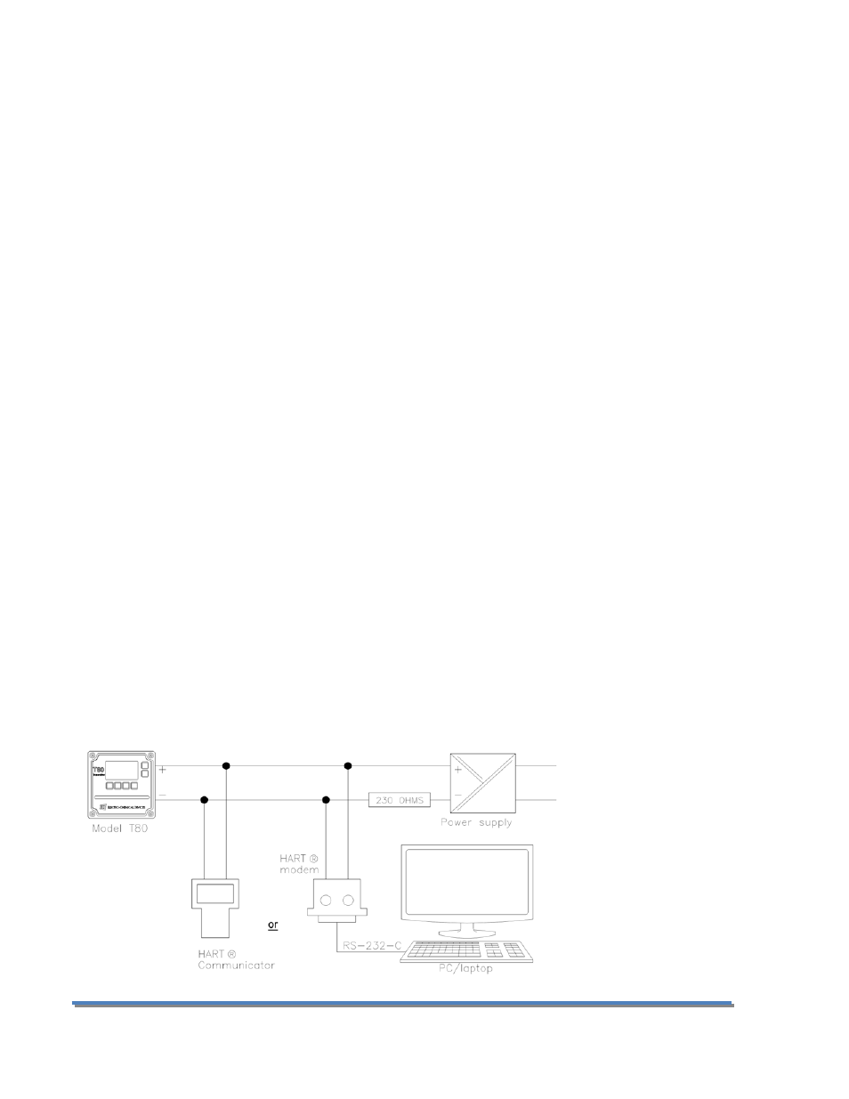
Transmitters with HART® Communication can be wired as shown below. See HART® Communication menu in
Appendix 9.2:
Page 19
Model T80