Menus of inputs/ outputs, Can 1 input, Menus of inputs/outputs – Flowserve SPECTORcontrol User Manual
Page 27
27
Menus of Inputs/ Outputs
CAN 1..10 input
To adjust the inputs / outputs press button
in the menu
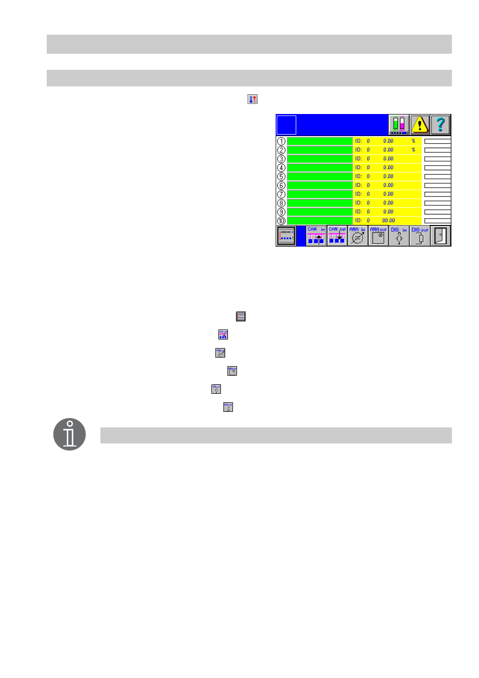
Overview
.
1.
The green input fields list the names of the
current CAN inputs. Active inputs are indi-
cated by the illuminated yellow number on
the left side. A node ID conflict is indicated
by a mark at the left side of the ID setting.
At the right side the currently measured val-
ue, the associated unit and the graphical
representation is shown. Current alarms
are indicated for each individual input by a
mark at the left side of the graphical repre-
sentation.
2.
To re-configure an input click in the green input field. The menu
CAN Type 1...10
pops up.
If one input has already been configured its designation will appear in the input field.
Click in the input field to call up the corresponding menu directly.
■
To show the control equipment press
.
■
To call up the CAN outputs press
.
■
To show the analog inputs press
.
■
To call up the analog outputs press
.
■
To show the digital inputs press
.
■
To call up the digital outputs press
.
CAN 1..10
Input
Logo
Note
CAN input 1 is linked with level indication and CAN input 2 with conductivity
indication in the menu
Overview
.
The values of these devices are currently indicated in the menu
Overview
.