Analog 1 output, Analog output 1, Analog 1 output analog output 1 – Flowserve SPECTORcontrol User Manual
Page 43: Menus of inputs/ outputs
43
– con tinued –
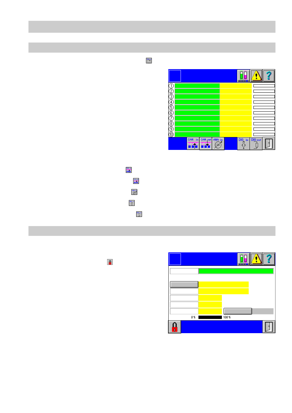
Analog 1..10 output
1.
In the menu Inputs or Outputs press
.
2.
The green input fields list the names of the
current analog inputs. Active inputs are in-
dicated by the illuminated yellow number
on the left side. At the right side the current-
ly measured value, the associated unit and
the graphical representation are shown.
Current alarms are indicated for each indi-
vidual input by a mark at the left side of the
graphical representation.
3.
To configure an input click in the green in-
put field. The menu
Analog Output 1...10
pops up.
■
To show the CAN inputs press
.
■
To call up the CAN outputs press
.
■
To show the analog inputs press
.
■
To show the digital inputs press
.
■
To call up the digital outputs press
.
Analog output 1..10
1.
Click in the green input field of the menu
Analog 1..10 Output
.
2.
The menu
Analog Output 1...10
is pass-
word protected. Press
and enter your
password.
3.
To name the analog output click in the in-
put field
Name
.
4.
Use the on-screen keyboard to overwrite
or modify the value in the input mask.
5.
To select the type of signal press button
Type
. The available types of actual value
signal are shown in a list. After the selec-
tion the values of the sensing element will
be indicated.
Control outputs are established in the setup menu of the continuous controller. The
controller has always top priority.
6.
To activate or de-activate the analog output press button
AO On/Off
.
Analog 1..10
Output
Logo
0.00 %
0.00 %
0.00 %
0.00 %
0.00 %
0.00 %
0.00 %
0.00 %
0.00 %
0.00 %
Analog
Output 1
Logo
specified by:
Name
Off
Range 100
Range 0
Type
AO On
Name
NC
0.0
0.0
0.0 %
0
AO Off
Output value