Fronius Agilo 75.0 User Manual
Page 43
Advertising
41
EN
4x
L1
L2
L3
N
+
PE
Maximum fuse
rating on alternat-
ing current side
Connecting an
external AC sup-
ply for the invert-
er
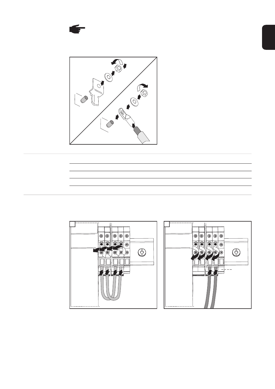
Procedure for connecting an external AC supply for the inverter (e.g. to provide an external
supply to controllers or fans):
1
2
*
If present, connect ground conductor to grounding terminal 9
NOTE! Ensure that the phases are connected in the right order: L1, L2, L3, N and
PE.
After connecting the phases, check the rotary field of the grid using a rotary field
measuring device. The inverter is designed for a clockwise rotary field.
3
5
6
9
2
4
1
7
8
18 Nm
M10
M10
Inverter
Phases
Nominal output
Fuse protection
Fronius Agilo 75.0-3
3
100 kVA
3 x 200 A
Fronius Agilo 100.0-3
3
100 kVA
3 x 200 A
1 3
5 7
2 4
6 8
N
1
N
L
N
3
1
6 5
2 4
*
2
Advertising
This manual is related to the following products: