Controls and indicators – Fronius Agilo 75.0 User Manual
Page 61
59
EN
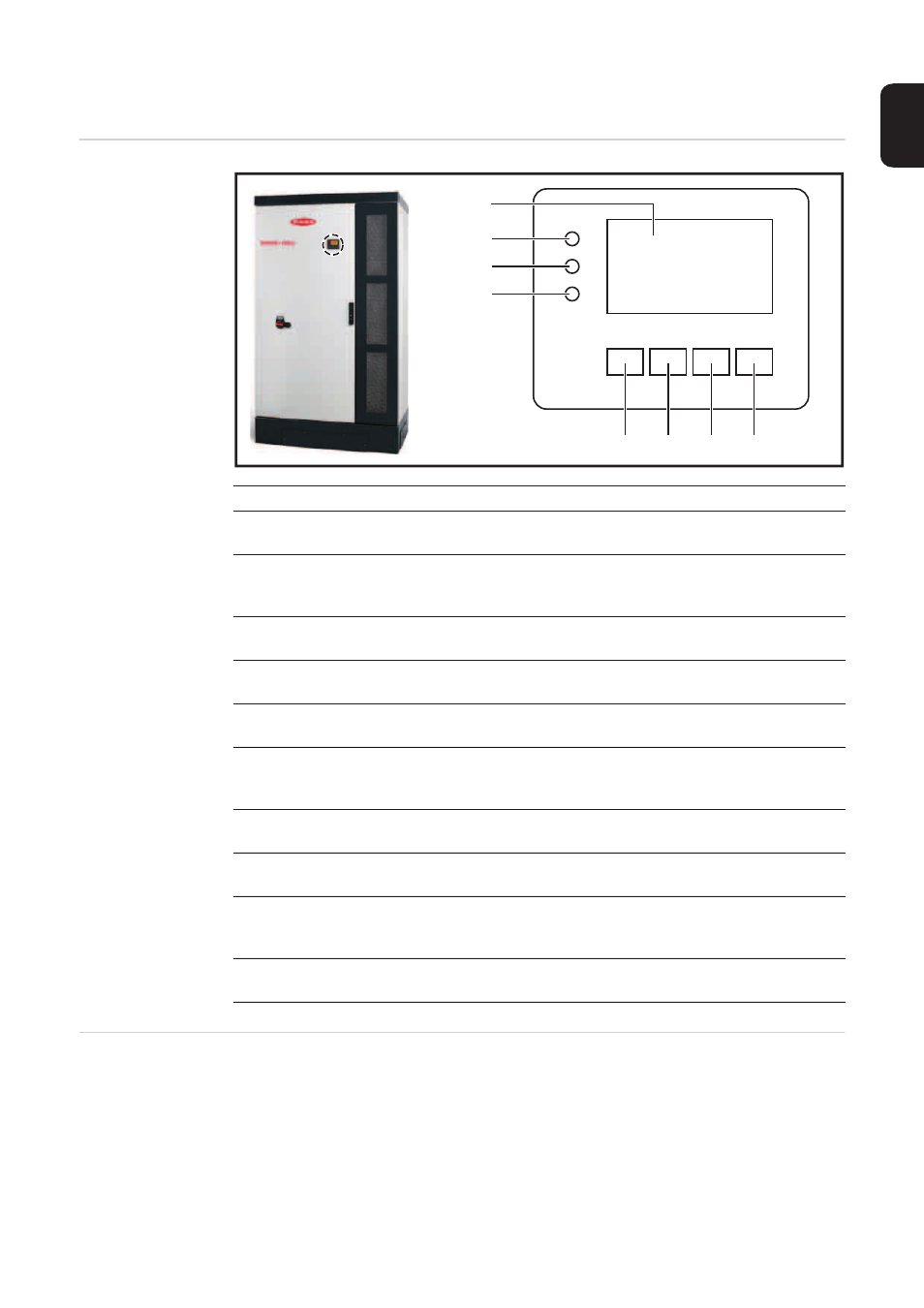
Controls and indicators
Controls and indi-
cators
Display
Power for the display comes from the mains voltage. The display is therefore available per-
manently.
Item
Description
(1)
Display
for displaying values, settings and menus
Monitoring and status LEDs
(2)
General status LED (red)
lights when there is a status code on the display
(3)
Startup LED (orange)
for displaying whether the inverter is in its startup phase or is on standby
(4)
Operating state LED (green)
for displaying the operating state
Function keys - allocated different functions depending on the selection:
(5)
'Left/up' key
for navigating to the left and up
(6)
'Down/right' key
for navigating down and to the right
(7)
'Menu/Esc' key
for switching to the menu level
for quitting the Setup menu
(8)
'Enter' key
for confirming a selection
(1)
(2)
(3)
(4)
(5)
(6)
(7)
(8)
IMPORTANT! The display on the inverter is not a calibrated measuring device. A slight in-
accuracy of a few percent from the energy meter used by the energy supply company is
intrinsic to the system. A calibrated meter will be needed to calculate the bills for the energy
supply company.