Installation - concentric venting (horizontal) – Greenheck IG / IGX (464104 IOM) (Pre-2009) User Manual
Page 11
11
Step 1 Determine Venting Location
Determine the location of the concentric venting adapter (CVA) based on any clearances that must be maintained
(follow all codes referenced in these instructions).
Step 2 Attach Mounting Brackets
Attach field supplied, corrosion resistant mounting brackets to the CVA using corrosion resistant sheet metal
screws.
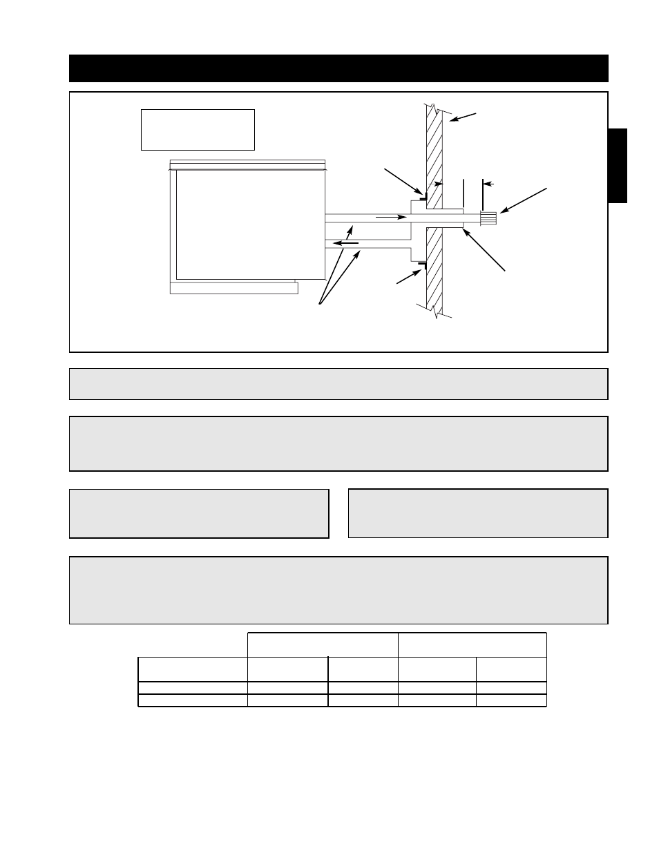
Installation - Concentric Venting (Horizontal)
EXHAUST
COMBUSTION AIR
Exterior Wall
Mounting
Bracket
Mounting
Bracket
A
B
Exhaust Pipe
Terminal
A = 2 inch minimum
B = 12 inch minimum
Combustion Air
Inlet Guard
Pitch vent pipe downward from
furnace .25 inches per foot
NOTE!
All vent piping is FIELD SUPPLIED by others and
is not supplied by Greenheck.
NOTE!
The optional venting kit includes a concentric
venting adapter (CVA), vent terminal and guard.
NOTE!
Maintain at least 12 inches from the combustion air inlet guard to the vent terminal.
NOTE!
To prevent water from running into the combustion air pipe and to allow for easy installation of the
combustion air guard, the combustion air pipe must terminate at least 2 inches from the exterior
surface of the outside wall.
Non-Concentric
Concentric
Vent Connection Diameter
Vent Connection Diameter
Furnace Size
Exhaust
Combustion
Exhaust
Combustion
(MBH)
(Inches)
Air (Inches)
(Inches)
Air (Inches)
75 -175
4
4
4
6
200 -400
6
6
6
8
Installation
IMPORTANT!
Vent terminals must be used. Construct the vent system as shown in drawings and reference the
tables for the correct vent pipe diameters. The minimum vent length is 5 feet and the maximum vent
length is 70 feet. The total equivalent vent length must include elbows. The equivalent length of a 4
inch elbow is 6 feet and the equivalent length of a 6 inch elbow is 10 feet.