Reference - model ig (single or 2 stage) – Greenheck IG / IGX (464104 IOM) (Pre-2009) User Manual
Page 82
82
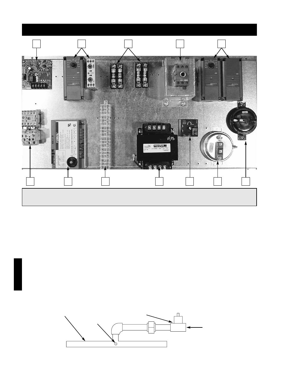
Reference - Model IG (Single or 2 Stage)
3
⁄
4
inch Gas Supply
Connection
Staged Gas
Valve
Manifold
Gas Pressure
Test Port
Reference
1
6
7
8
9
10
11
12
2
3
4
5
1.
Building Freeze Protection - Prevents the discharge of cold air into the building
2.
Evaporative Cooling Controls (Optional) - Controls the evaporative cooler.
3.
Fusing - Provides 24 VAC fusing for controls and fusing for the combustion blower.
4.
Main Disconnect - Provides single point power connection to the unit.
5.
Stage Controller - Provides single or two stage control of the furnace.
6.
Motor Starter(s) - Magnetic contact(s) for starting motor(s). Comes standard with electronic overload,
auxiliary contact(s) optional.
7.
Ignition Controller - Controls the ignition of the furnace. Maintains safe operation of the furnace.
8.
Terminal Strip - Provides easy, number coded wiring of the control.
9.
Main Transformer - Provides 24 VAC for controls.
10. Time Delay - Temporarily runs the combustion blower after the furnace has shut down (post-purge).
11. Dirty Filter Switch - Switch trips when filter are dirty and pressure loss is higher than set point.
12. Airflow Switch - Monitors the airflow inside the heat exchanger.
13. Inlet Air Sensor (not shown) - Shuts down furnace when the outside air is above the set point.
14. Grounding Lugs (not shown) - Completes electrical circuit.
15. Heat/Cool Relay (not shown) - Passes power to the furnace or cooling controls.
NOTE!
This is a typical blower control center, the control center in your unit may be different. Reference the
ladder diagram on the inside of the control center door for a unit specific wiring diagram.