Greenheck IG / IGX (464104 IOM) (Pre-2009) User Manual
Page 28
28
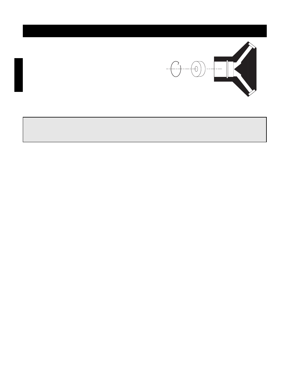
Step 1 Verify Nozzle Placement
Inspect the refrigerant distributor and verify that the
nozzle is in place. The nozzle is generally held in
place by a retaining ring or is an integral part of the
distributor itself.
Step 2 Install the Optional Hot Gas Bypass Kit (By Others)
If a hot gas bypass kit was ordered with the coil, install it now. Consult the IOM from the bypass kit supplier for
complete installation instructions. Align the side port with the hot gas line prior to brazing into place.
Step 3 Install Suction Line
Install a suction line from the compressor to the suction connection.
Step 4 Install the Thermal Expansion Valve (TEV) (By Others)
Follow the TEV manufacturer’s recommendations for installation to avoid damaging the valve. If the valve is
externally equalized, use a tubing cutter to cut off the plugged end of the factory installed equalizer line. Use a
de-burring tool to remove any loose metal from the equalizer line and attach it to the TEV. If the valve is
internally equalized, the factory installed equalizer line can be left as is.
Step 5 Mount the Remote Sensing Bulb (By Others)
The expansion valve’s remote sensing bulb should be securely strapped to the horizontal run of the suction line
at the 3 or 9 o’clock position and insulated.
Installation - Direct Expansion Coil Piping (Optional)
Retainer
Ring
Nozzle
Distributor
NOTE!
If a hot gas bypass kit was ordered, the nozzle will not be located in the distributor, it will be located in
the hot gas bypass kit.
Installation