Greenheck IG / IGX (464104 IOM) (Pre-2009) User Manual
Page 31
31
Step 1 Mount Pressure Tap
Using the factory provided bracket, mount the
pressure tap to the outside of the unit. Choose a
location out of the prevailing winds and away from
supply or exhaust fans to assure accurate readings.
Step 2 Run Pressure Tap Lines
Run a pressure tap line from the pressure tap on the
outside of the unit to the low pressure tap on the
back of the photohelic gauge. Run a second pressure
tap line from the high pressure tap on the back of the
photohelic gauge to the space. Fifty feet of tubing is
supplied with the unit.
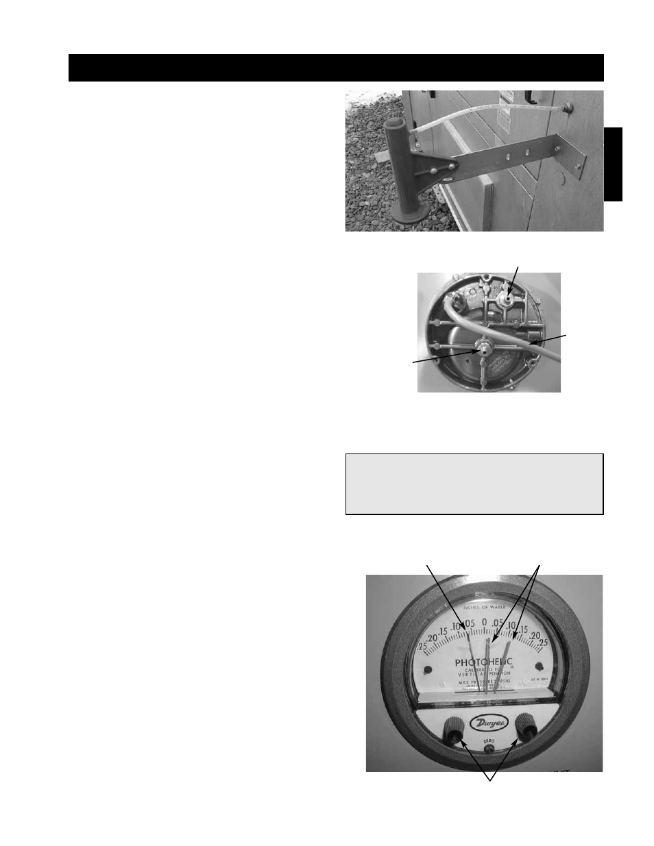
Step 3 Set the Building Pressure
The pressure gauge (pictured bottom right) is used to
set the desired building pressure. The pressure is set
by adjusting the knobs for the upper and lower
pressure limits. Typical settings are 0.0 inch wc for
the lower and 0.10 inch wc for the upper pressure
setting.
Step 4 Check Control System
Before the unit is left in service, the recirculation
control system should be tested.
Turn both knobs to the upper most pressure setting.
You may have to remove the outdoor pressure tap
tubing. The return air damper should close (VAV
systems should go to max speed).
Set both knobs at the lowest setting, and the damper
should open (VAV systems should go to minimum
speed). It may take one to two minutes for the
damper to reach the desired position.
Reset the correct pressure limits before starting the
unit.
The picture on the bottom right shows a typical
photohelic setting. The needle in this photo indicates
a negative building pressure. During correct operation
the indicating needle will remain between or near the
setting needles.
Installation - Building Pressure Control (Optional)
Low
Pressure Tap
To Outside
Factory
Wiring
High Pressure Tap
To Space
Pressure Setting Knobs
Pressure Setting
Needles
Pressure Indicating
Needle
Installation
NOTE!
Blower start-up (S-1), steps 1-4 should be
performed before the blower is run.