Installation - concentric venting (vertical) – Greenheck IG / IGX (464104 IOM) (Pre-2009) User Manual
Page 13
13
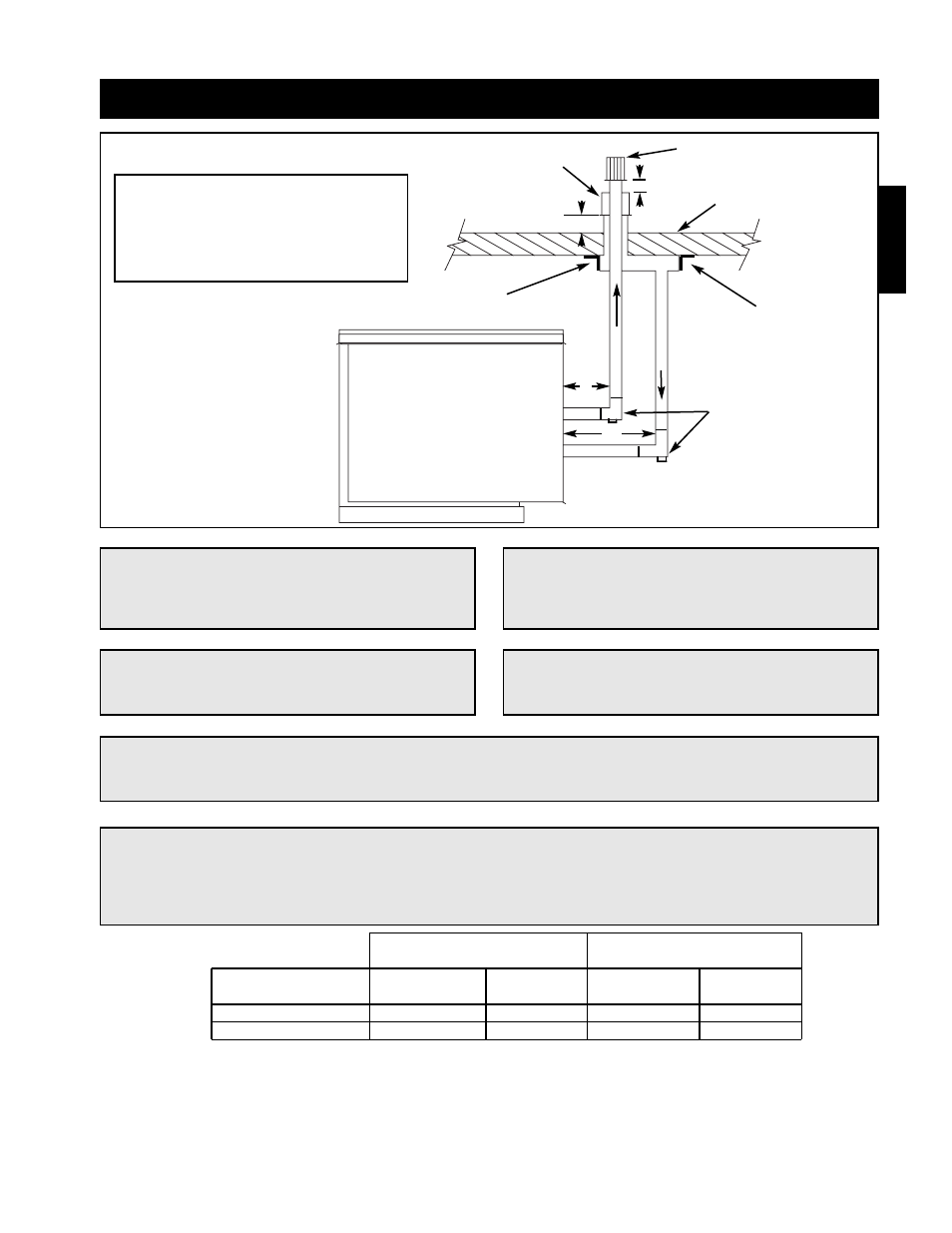
Installation - Concentric Venting (Vertical)
NOTE!
All vent piping is FIELD SUPPLIED by others.
Exhaust Vent Terminal
Combustion Air
Inlet Terminal
A
C
C
B
Roofline
EXHAUST
COMBUSTION AIR
Tee with drip leg and
cleanout cap
A = 12 inch minimum, but should size
according to expected snow depth.
B = 12 inch minimum
C = 12 inch minimum
NOTE!
Maintain at least 12 inches of clearance between
the top of the combustion air inlet terminals and
the bottom of the exhaust terminal.
NOTE!
A tee with clean-out must be provided on the combustion air and exhaust pipe to prevent debris from
entering the heat exchanger.
NOTE!
The bottom of the combustion air intake pipe
must terminate above the snow line, or at least
12 inches above the roof, whichever is greater.
Mounting
Bracket
Mounting
Bracket
Step 1 Determine Venting Location
Determine the location of the concentric venting adapter (CVA) based on any clearances that must be maintained
(follow all codes referenced in these instructions).
Step 2 Attach Mounting Brackets
Attach field supplied corrosion resistant mounting brackets to the CVA.
NOTE!
The optional venting kit includes a concentric
venting adapter (CVA), and two terminals.
Installation
IMPORTANT!
Vent terminals must be used. Construct the vent system as shown in drawings and reference the
tables for the correct vent pipe diameters. The minimum vent length is 10 feet and the maximum vent
length is 70 feet. The total equivalent vent length must include elbows. The equivalent length of a
4 inch elbow is 6 feet and the equivalent length of a 6 inch elbow is 10 feet.
Non-Concentric
Concentric
Vent Connection Diameter
Vent Connection Diameter
Furnace Size
Exhaust
Combustion
Exhaust
Combustion
(MBH)
(inches)
Air (inches)
(inches)
Air (Inches)
75 -175
4
4
4
6
200 -400
6
6
6
8