3 wiring diagrams, Wiring diagrams – MicroE Mercury II 6000 User Manual
Page 26
Appendix
IM-Mercury_II_6000 Series Rev. 1
Page 25
©2014 MicroE Systems
Mercury
II
6000 Series Encoders
Installation Manual and Reference Guide
Maximum Quadrature Output Frequency
Output Frequency (MHz)
A-Quad-B Output Rate
(millions of states/sec)
Dwell Time (or edge separation)
(µsec)
12.50
50.00
0.02
6.25
25.00
0.04
3.125
12.50
0.08
1.563
6.25
0.16
0.781
3.125
0.32
0.391
1.5625
0.64
0.195
0.78125
1.28
0.098
0.390625
2.56
0.049
0.1953125
5.12
0.024
0.09765625
10.24
Note*: Values shown are approximate. Exact values may be calculated using either of the
following equations:
𝑂𝑢𝑡𝑝𝑢𝑡 𝐹𝑟𝑒𝑞𝑢𝑒𝑛𝑐𝑦 = 12.5𝑀𝐻𝑧/2^𝑛
where n = number of steps below 12.5MHz
𝑂𝑢𝑡𝑝𝑢𝑡 𝑅𝑎𝑡𝑒 = 50/2^𝑛
where n = number of steps below 50 million states per second
7.3
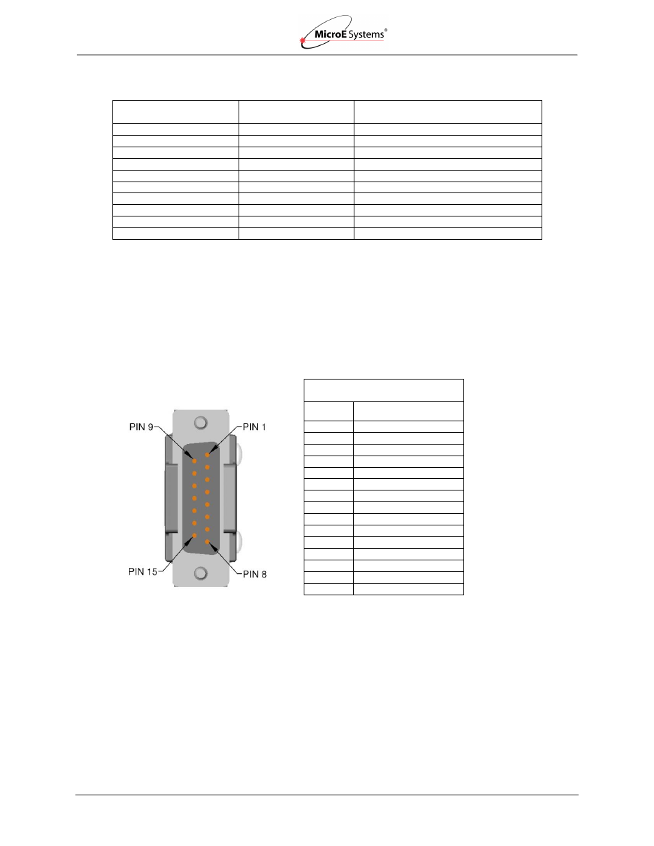
Wiring Diagrams
15-Pin Standard Male D-sub Connector Configuration
Mercury II 15P D-Sub Pinouts
Quad Output
Pin
Function
1
Right Limit+
2
GND
3
Right Limit-
4
Index-
5
B-
6
A-
7
+5V
8
+5V
9
GND
10
Left Limit+
11
Left Limit-
12
Index+
13
B+
14
A+
15
Alarm
Note: Alarm: A and B are tri-stated if the encoder signal becomes too low for reliable operation
and pin 15 goes high to 3.3V.
Note: GND and Inner Shield are internally connected.