MicroE Mercury II 6000 User Manual
Page 35
Appendix
IM-Mercury_II_6000 Series Rev. 1
Page 34
©2014 MicroE Systems
Mercury
II
6000 Series Encoders
Installation Manual and Reference Guide
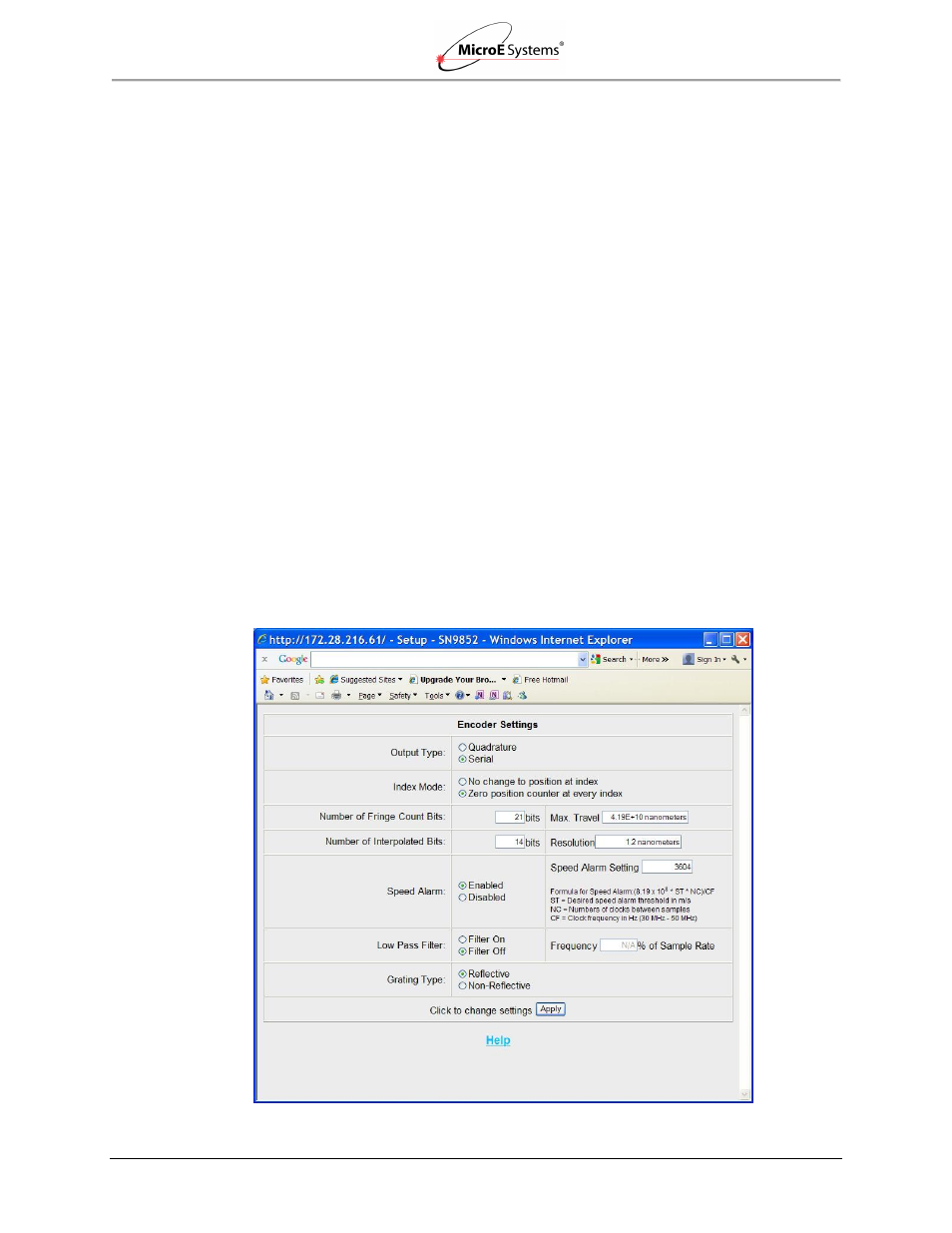
Configurable Settings
There are a number of settings that may be configured for serial output operation:
Index mode: The encoder can be set to reset the position to 0 every time the index is
crossed (“Index Mode 1”) or to use the position at power up as the 0 position (“Index
Mode 0”).
Number of fringe count bits: Each fringe is 20µm long on the encoder’s scale. The
number of fringe count bits can be set from 0 bits (no fringes) to 21 bits (2,097,152
fringes). Use enough fringe count bits to ensure that the position word is large enough for
the expected range of motions. For example, 18 fringe count bits will make the range of
position values from -2.62144m to +2.62144m (total travel of 5.24288m). The total travel
in meters is calculated as follows: travel = 0.00002m * 2n, where n = the number of
interpolation bits.
Number of interpolated bits: The number of bits to calculate the position within a fringe,
and thus the encoder’s resolution. The number of interpolated bits can be set from 2 bits
(x4 interpolation; 5µm resolution) to 14 bits (x16, 384 interpolation; approximately 1.22
nm resolution). Using fewer fringe count and interpolation bits than the maximums can
increase the sample rate to the controller. The encoder’s resolution, in µm, is calculated
as follows: Resolution = 20µm/2n, where n = the number of interpolation bits.
Low pass filter: The digital low pass filter is used to limit the bandwidth of the encoder
system if desired. It is set in terms of % of sample rates and can be set from 0.01% to
40% in 0.01% increments.
Note: Fringe count bits + interpolated bits must be
≥ 4 bits total.