8 troubleshooting, Troubleshooting – MicroE Mercury II 6000 User Manual
Page 38
Appendix
IM-Mercury_II_6000 Series Rev. 1
Page 37
©2014 MicroE Systems
Mercury
II
6000 Series Encoders
Installation Manual and Reference Guide
7.8
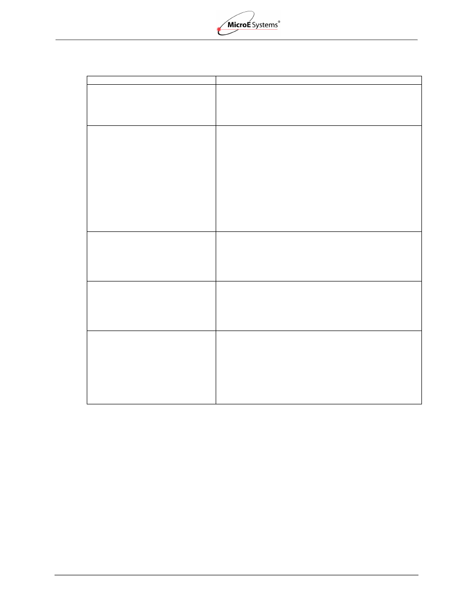
Troubleshooting
Problem
Solution
The Power/Calibration indicator will not
come on.
Make sure that the SmartPrecision II Electronics 15-pin D-
sub connector is fully seated and connected.
Confirm that +5 Volts DC is being applied to pin 7 and 8 on
the SmartPrecision II electronics 15-pin connector and that
pins 2 and 9 are connected to ground.
Can't get the SmartPrecision II
Electronics "Signal" LEDs better than
red or yellow; or the green
“Proper
Alignment” indicator doesn't stay
illuminated over the full length of the
scale.
Verify that the sensor is mounted in the correct orientation
with reference to the scale and scale mounting reference
edge. Refer to the Interface Drawing.
Verify that the sensor has been aligned to the scale and
that the mounting screws are tight. Check the dimensions
for the mechanical mounting holes (and clamps if any) to
make sure that the sensor is correctly located over the
scale in the Y
and Z dimensions. Refer to the Interface
Drawing.
Check that the scale is firmly mounted and can't jiggle or
move in any direction other than the axis of motion.
Make sure that the scale is clean over its entire length or
circumference.
The green Power/Calibration indicator
LED or limit LEDs are flashing
unexpectedly.
Part of the normal setup procedure is to activate the
SmartPrecision II Electronics Calibration/Setup process by
pressing the recessed button in the electronics module.
The Power/Cal. LED or limit LEDs will begin to flash until
the relevant setup process is complete. See the
instructions beginning at
Section 5.1.1 Sensor Alignment
Can't complete the Calibration/Setup
process - the green Power/Calibration
indicator doesn't stop flashing.
Verify that the sensor is mounted in the correct orientation
to the scale for the desired index mark. Refer to the
Interface Drawing.
Section 4.2 Verify Sensor Mounting Surface
to ensure proper sensor alignment and index
marker operation.
Signal Plots in Smart Precision II
Software not displaying in browser
window.
Reduce the Security Level setting for Java to “Medium” by
going to the Windows Start Menu/Control Panel/Java and
selecting the Security tab.
You may receive an Application Blocked by Security
Settings message when attempting to load the plotApplet.
Warning: Reducing the Security Level in the Security Tab may
decrease protection of your computer against malicious
software.