MicroE Mercury II 6000 User Manual
Page 29
Appendix
IM-Mercury_II_6000 Series Rev. 1
Page 28
©2014 MicroE Systems
Mercury
II
6000 Series Encoders
Installation Manual and Reference Guide
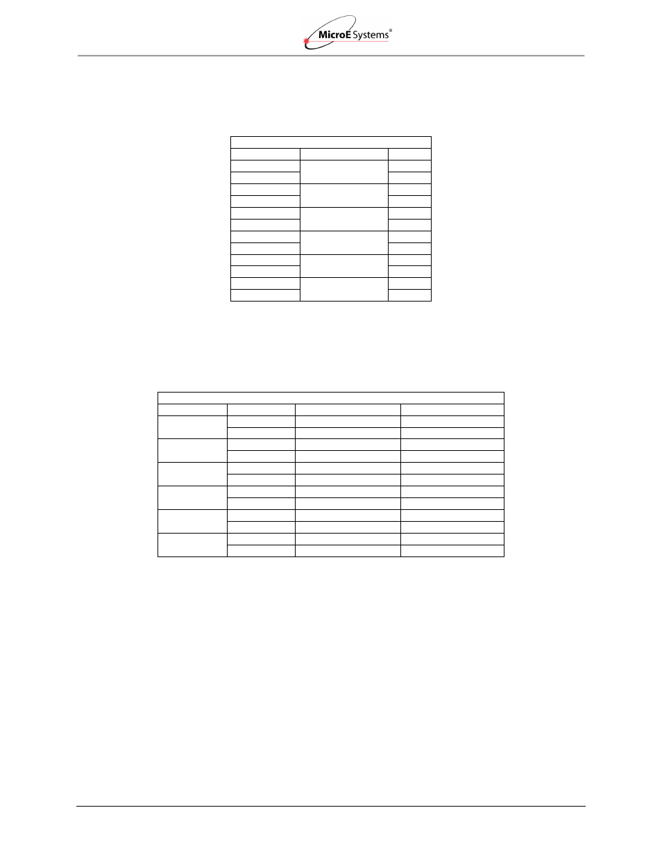
Signal Wiring for A-quad-B
Each differential signal should be connected to a corresponding twisted pair as follows for the 15-
pin standard male D-sub connector:
Note: The Alarm signal on pin 15 is not differential and is not part of a pair.
Signal Wiring for Serial Interface
Each differential signal should be connected to a corresponding twisted pair as follows:
Note: NC - No Connect
Mercury II 6000
Signal
Twisted Pair
Pin
A+
Pair 1
14
A-
6
B+
Pair 2
13
B-
5
Index+
Pair 3
12
Index-
4
Left Limit+
Pair 4
10
Left Limit-
11
Right Limit+
Pair 5
1
Right Limit-
3
+5V
Pair 6
7, 8
GND
2, 9
Mercury II 6800Si/Pa Signals
Twisted Pair
DB15 Pins
6800Si Signals
6800Pa Signals
Pair 1
14
SDATA_OUT+
NC*
6
SDATA_OUT-
NC
Pair 2
13
SCLOCK_OUT+
NC
5
SCLOCK_OUT-
NC
Pair 3
10
SCLOCK_IN+
REQ_SD+
11
SCLOCK_IN-
REQ_SD-
Pair 4
1
nCS+
NC
3
nCS-
NC
Pair 5
7
+5V
NC
8
+5V
NC
Pair 6
2
GND
NC
9
GND
NC