MicroE Mercury II 6000 User Manual
Page 33
Appendix
IM-Mercury_II_6000 Series Rev. 1
Page 32
©2014 MicroE Systems
Mercury
II
6000 Series Encoders
Installation Manual and Reference Guide
Once it remains on continuously for at least 500ms, the sensor is ready for data transfers
and SCLOCK_OUT will remain stable.
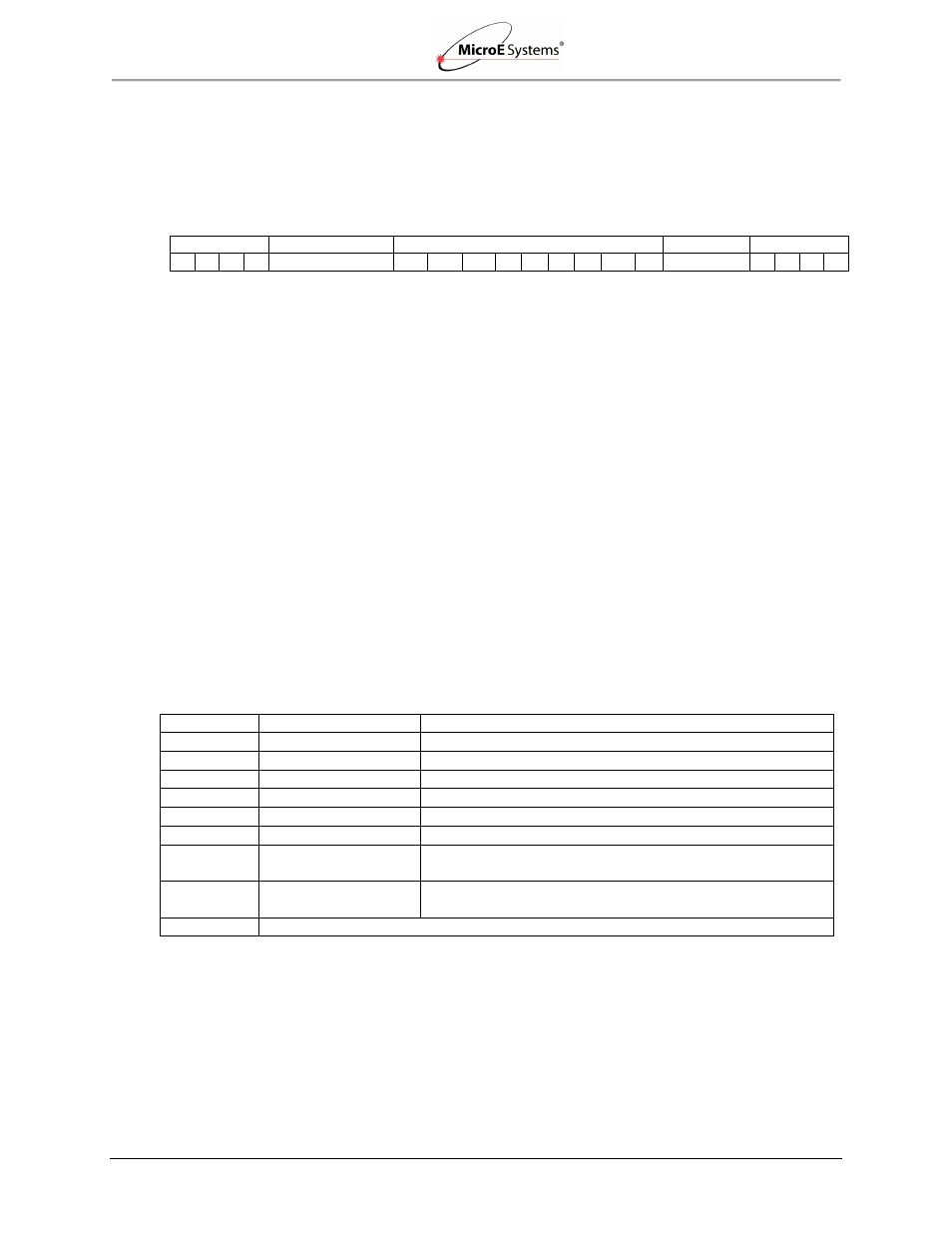
Data Word Format
First Bit ------------------------------------------------------------------------------------------------------------------------ Last Bit
Start Bit
Position Word
Status Bits
CRC Word
Stop Bits
1 0 1 1
4
– 35 Bits
IW RL LL
Y R S
C Sp
Ø
6 Bits
1 0 1 1
MSB--------------LSB
Start Bits
The data word will always start with bits one, zero, one, one.
Position Word
The 2’s complement position word has two sections and is user adjustable. The Inter-Fringe bits
which determine encoder resolution are adjustable between 14 bits (1.22nrm resolution) and 2
bits (5µm resolution). The Fringe-Counter bits are increments of 20µm which determine the total
travel and are adjustable between 21 bits (±21 meters) and 0 bits (±10 microns). The total
number of bits (inter-fringe + fringe-counter) must be at least 4 and no more than 35. Position
word length is edited via the SmartPrecision II software in the Status and Setup tab. The position
word is always transmitted most significant bit (MSB) first.
Status Bits
The encoder status bits are all active high with the exception of the Right and Left Limits. Limit
status is user programmable (active high or active low) by using the SmartPrecision II software in
the Calibrate and Align tab.
The nine status bits are defined as follows:
Status Bit
ID
Definition
IW
Index Window
Active when the sensor is over the optical index mark
RL
Right Limit
Active when the sensor is over the right limit marker
LL
Left Limit
Active when the sensor is over the left limit marker
Y
Yellow Alarm
Active during marginal alignment to the main track
R
Red Alarm
Active during poor or bad alignment to the main track
S
Saturation Alarm
Active if the main track signal is too large
C
Communication
Error
Active if there is a communication error internal to the
encoder
Sp
Over-Speed Alarm
Active if the encoder exceeds 10m/s (the speed alarm
threshold)*
Ø
Reserved bit is always zero
Example: ØØØØ_ØØØØ_Ø = normal operation, not at the index mark.
Note*: The encoder maximum operational speed is 10 meters/second, regardless of the speed
alarm setting. The alarm is a user configured feature, to be set for specific application
requirements, or the bit may be ignored if desired. The speed alarm is dependent on the
clock frequency, the sample rate, and the desired speed where the user would like the bit
to assert high. The speed alarm register is defaulted to 3604, and may be changed using