0 system overview, 1 system view, 2 expanded view – MicroE Mercury II 6000 User Manual
Page 6: System overview, System view, Expanded view
Advertising
System Overview
IM-Mercury_II_6000 Series Rev. 1
Page 5
©2014 MicroE Systems
Mercury
II
6000 Series Encoders
Installation Manual and Reference Guide
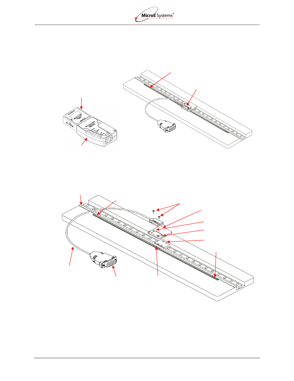
3.0 System Overview
This section identifies parts for the sensor installation.
3.1
System View
3.2
Expanded View
Index Marker
15-Pin Male
D-Sub Connector
Double-Shielded
Cable
Left Limit Marker
Scale Mounting Surface Reference Edge (Benching Surface)
Tape Scale: shown mounted on
a fixed (non-moving) substrate.
Sensor: shown mounted on a
linear bearing using a
mounting bracket.
Alignment Tool
Sensor Connector
Mounting Screws
Typical User-Supplied
Sensor Mounting Bracket
Sensor Mounting Holes
Sensor Benching Pins
Bracket Mounting Holes
Right Limit Marker
Alignment Tool Adapter
Advertising