3 install linear glass scales, Install linear glass scales, 3 install – MicroE Mercury II 6000 User Manual
Page 67: Linear glass scales
PurePrecision Linear Glass Scales Installation
IM-Mercury_II_PurePrecision_Scales Rev. 1
Page 23
©2014 MicroE Systems
Mercury II PurePrecision Tape and Glass Scales
Installation Manual and Reference Guide
Step
Action
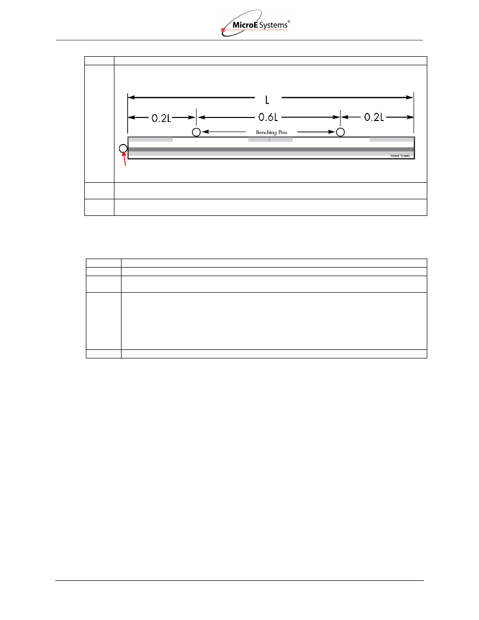
2. Two benching pins are recommended on the long side of the scale and one at the end as shown
below. “Benching" the scale to the system means aligning the scale by means of benching pins.
3. Position the benching pins inward from either end of the scale. 20% of the overall scale length is
the recommended location from the edge.
4. Be sure the benching pins do not exceed the height of the scale to prevent mechanical
interference with the sensor or sensor mount.
4.3
Install
Linear Glass Scales
Use the following instructions to install linear glass scales.
Step
Action
1. Make sure that the mounting surface is dry and clean.
2. Align the scale by placing the edges against the benching pins. Optionally, scale clamps may
be used to secure the scale while the adhesive cures.
3. Apply a hard epoxy, such as Tra-Bond 2116, at one point on the scale. If no end benching pin
is used, epoxy at the index mark is suggested. If an end benching pin is used, epoxy at the end
of the scale where the pin is located is suggested. Then apply 100% Silicone RTV adhesive
around the edges of the scale.
Caution: Do not allow epoxy to seep under the scale as this will affect scale flatness and
therefore, encoder accuracy.
4. After adhesive curing, remove the scale mounting clamps.
If installing Laser Tape II index/limits, continue to the next section.
End Benching Pin (optional)