MicroE Mercury II 6000 User Manual
Page 27
Appendix
IM-Mercury_II_6000 Series Rev. 1
Page 26
©2014 MicroE Systems
Mercury
II
6000 Series Encoders
Installation Manual and Reference Guide
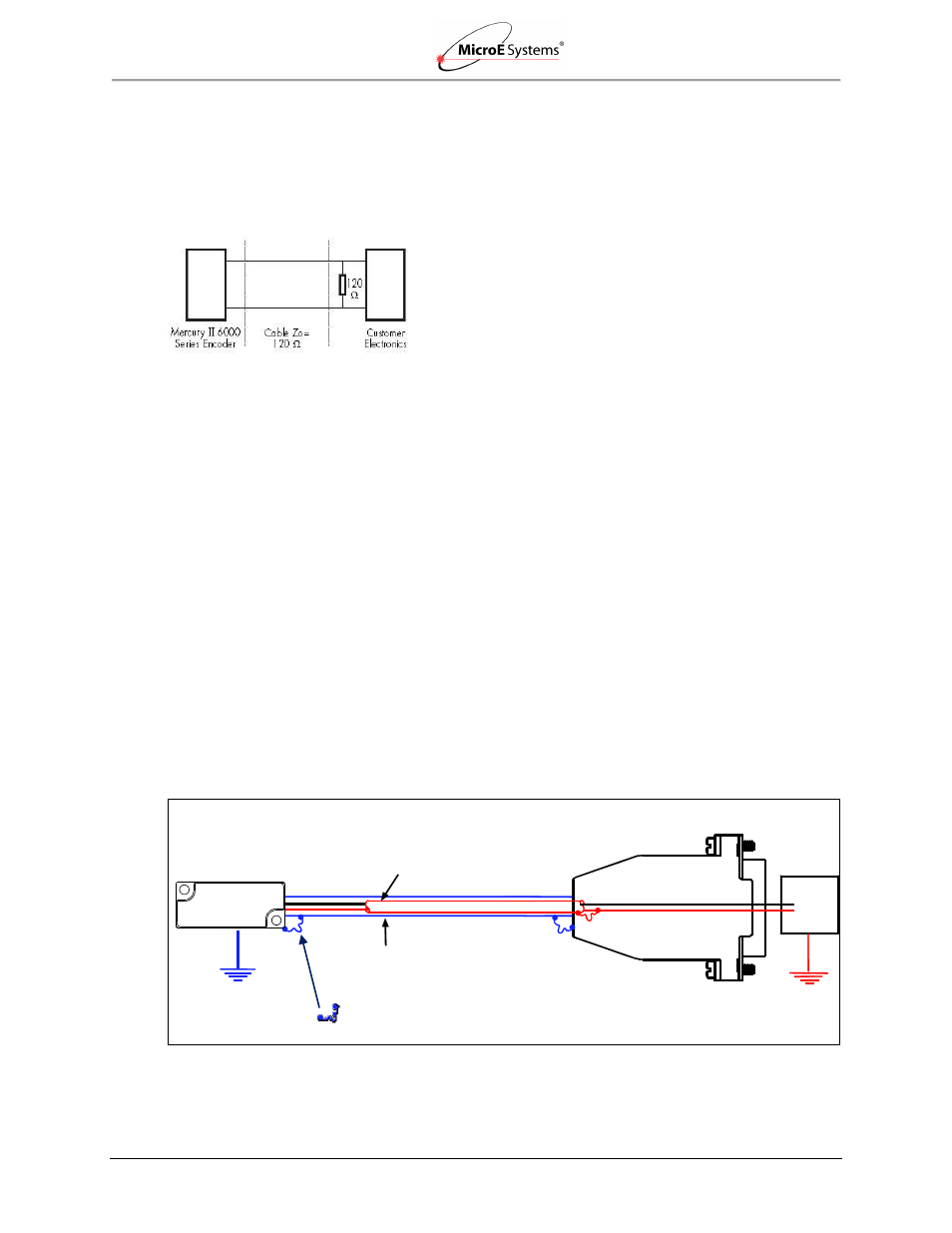
Recommended Interface Termination
Customer Differential Line Receiver
– RS 422: The following diagram shows the recommended
signal termination for a-quad-b, serial, index, and limits signals for the Mercury II 6000 Series
Encoders. Standard RS-422 Line Receiver Circuitry:
Grounding Considerations
The diagrams below show how to make the connections when the encoder's connector is
plugged into the customer's controller chassis. If a customer-supplied extension cable is used, it
should be a double-shielded cable with conductive connector shells and must provide complete
shielding over the conductors contained within it over its entire length. Furthermore, the shields
should be grounded at the connection to the controller chassis the same way as the encoder
connectors in the diagrams below.
Note: For best performance, isolate the encoder outer shield from motor cable shields and
separate the encoder cable as far possible from motor cables.
Sensor mounted with good electrical contact to a well-grounded surface (preferred)
The encoder's connector shell must be in close, electrically-conductive contact with the customer-
supplied mating connector, which must be isolated from the controller's ground. If a customer-
supplied shielded cable connects the encoder to the controller, then the outer shield on the
customer-supplied cable must be isolated from the controller's ground.
The sensor mounting surface must have a low-impedance (DC/AC) connection to ground. The
encoder sensor mounting surface may have to be masked during painting or anodizing to ensure
good electrical contact with the sensor.
Inner Shield: Insulated from outer shield, sensor
case, and connector housing. Connected to circuit
common internally as supplied by MicroE Systems.
Electrically conductive mechanical connection
(as supplied by MicroE Systems).
5 Volts
O Volts
Outer Shield: Connector to sensor and
connector housing.
Power
Supply