Vcm controller technical guide 13, Warning – Orion System VCM Controller User Manual
Page 13
VCM Controller
Technical Guide
13
R20
C8
TB2
D3
PWR LD1
24V
AC-IN
24V
AC-IN
GND
GND
GND
TB1
PJ2
+24VDC-OUT
R17
PJ1
R15
UL5A250V
AC
G5L-114P
-PS
OMRON
CONTACT
:
24VDC
UL5A250V
AC
G5L-114P
-PS
OMRON
CONTACT
:
24VDC
UL5A250V
AC
G5L-114P
-PS
OMRON
CONTACT
:
24VDC
UL5A250V
AC
G5L-114P
-PS
OMRON
CONTACT
:
24VDC
K3
K2
4RLY IO BD.
V4
K4
YS101790
TB1
V1
K1
K3
U2
K4
RN1
PCF8574P
U1
ULN2803A/
K2
K1
74HC04N
P1
CX2
CX1
UL5A250V
AC
G5L-114P
-PS
OMRON
CONTACT
:
24VDC
UL5A250V
AC
G5L-114P
-PS
OMRON
CONTACT
:
24VDC
UL5A250V
AC
G5L-114P
-PS
OMRON
CONTACT
:
24VDC
UL5A250V
AC
G5L-114P
-PS
OMRON
CONTACT
:
24VDC
K3
K2
4RLY IO BD.
V4
K4
YS101790
TB1
V1
K1
K3
U2
K4
RN1
PCF8574P
U1
ULN2803A/
K2
K1
74HC04N
P1
CX2
CX1
UL5A250V
AC
G5L-114P
-PS
OMRON
CONTACT
:
24VDC
UL5A250V
AC
G5L-114P
-PS
OMRON
CONTACT
:
24VDC
UL5A250V
AC
G5L-114P
-PS
OMRON
CONTACT
:
24VDC
UL5A250V
AC
G5L-114P
-PS
OMRON
CONTACT
:
24VDC
K3
K2
4RLY IO BD.
V4
K4
YS101790
TB1
V1
K1
K3
U2
K4
RN1
PCF8574P
U1
ULN2803A/
K2
K1
74HC04N
P1
CX2
CX1
UL5A250V
AC
G5L-114P
-PS
OMRON
CONTACT
:
24VDC
UL5A250V
AC
G5L-114P
-PS
OMRON
CONTACT
:
24VDC
UL5A250V
AC
G5L-114P
-PS
OMRON
CONTACT
:
24VDC
UL5A250V
AC
G5L-114P
-PS
OMRON
CONTACT
:
24VDC
K3
K2
4RLY IO BD.
V4
K4
YS101790
TB1
V1
K1
K3
U2
K4
RN1
PCF8574P
U1
ULN2803A/
K2
K1
74HC04N
P1
CX2
CX1
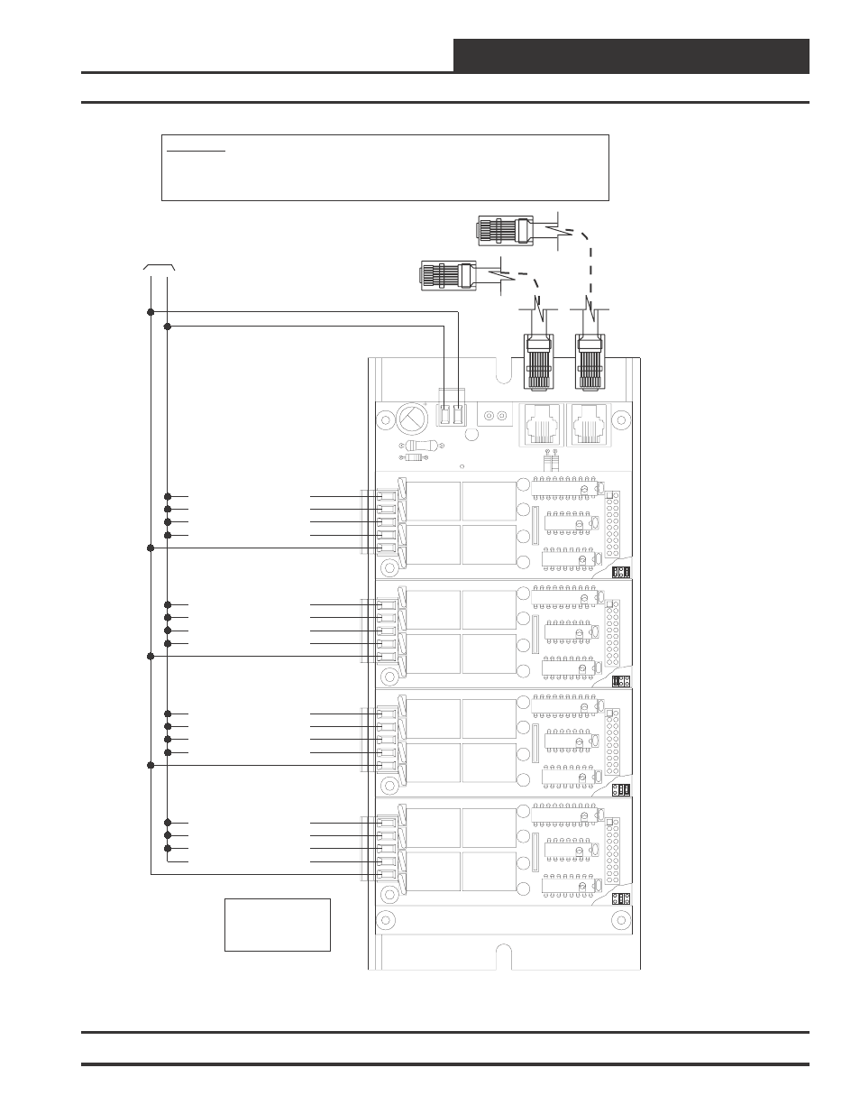
Configurable Relay Output # 6
Configurable Relay Output # 10
Configurable Relay Output # 14
Configurable Relay Output # 18
Configurable Relay Output # 7
Configurable Relay Output # 11
Configurable Relay Output # 15
Configurable Relay Output # 19
Configurable Relay Output # 8
Configurable Relay Output # 12
Configurable Relay Output # 16
Configurable Relay Output # 20
Configurable Relay Output # 9
Configurable Relay Output # 13
Configurable Relay Output # 17
Configurable Relay Output # 21
24
V
A
C
GND
Note:
All Relay Outputs Are
Normally Open And Rated
For 24 VAC Power Only.
2 Amp Maximum Load.
OE357
-
4
Relay
Output
Board
OE357
-
4
Relay
Output
Board
OE357
-
4
Relay
Output
Board
OE357
-
4
Relay
Output
Board
Modular Cable
Connect To VCM Controller
Modular Cable Connect To
Next Expansion Base Board
(When Used)
10 VA Minimum Power Required For
Each OE352 - 2 Slot Expansion Base Board.
20 VA Minimum Power Required For
Each OE353 - 4 Slot Expansion Base Board
WARNING!!
Observe Polarity! All boards must be wired with GND-to-GND and 24VAC-to-24VAC. Failure to observe
polarity will result in damage to one or more of the boards. Expansion Boards must be wired in such a way that
power to both the expansion boards and the controller are always powered together. Loss of power to the
expansion board will cause the controller to become inoperative until power is restored to the expansion board.
OE352 2 Slot Or OE353 - 4 Slot Expansion Board
As Required - OE353 Is Shown
Figure 8: Expansion Board Wiring Details For Relay Expansion Boards