Input/output wiring details, Technical guide vcm controller 20 – Orion System VCM Controller User Manual
Page 20
Technical Guide
VCM Controller
20
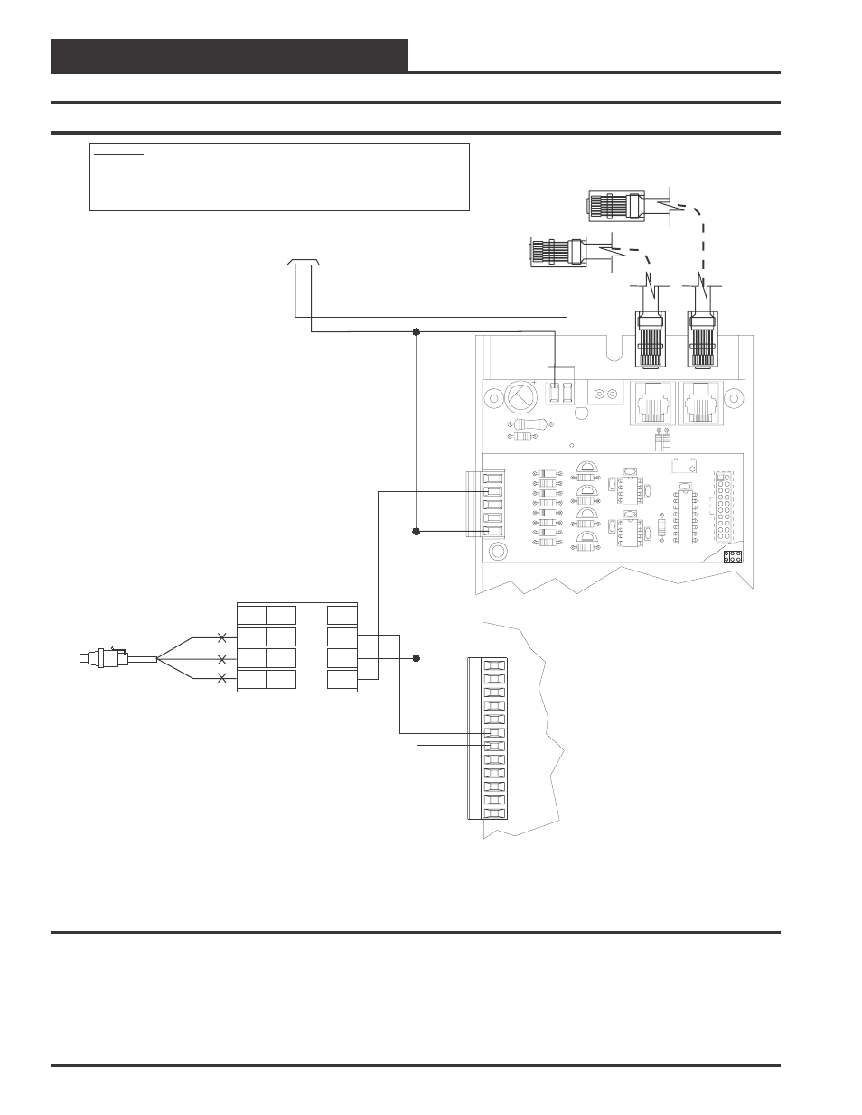
Input/Output Wiring Details
Figure 16: Suction Pressure Transducer Wiring (Units With Digital Compressors)
OE355
-
4
Analog
Output
Board
GND
AOUT2
1.5 to 5 VDC
24
V
A
C
GND
OE352 or OE353 Expansion Base Board
OE331-21-VCM
VCM Controller Board
10 VA Minimum Power Required For
Each 2 Slot Expansion Base Board.
20 VA Minimum Power Required For
Each 4 Slot Expansion Base Board
WARNING!!
Observe Polarity! All boards must be wired with GND-to-GND and 24VAC-to-24VAC. Failure
to observe polarity will result in damage to one or more of the boards. Expansion Boards
must be wired in such a way that power to both the expansion boards and the controller are
always powered together. Loss of power to the expansion board will cause the controller to
become inoperative until power is restored to the expansion board.
GND
INPUTS
GND
AOUT1
AOUT2
GND
+VDC
AIN1
AIN2
AIN3
AIN4
AIN5
AIN7
Copeland Digital
Compressor Controller
P4
RD
WH
BK
P3
P2
P1
SHLD
EXC
OUT
COM
P5
P6
C1
C2
R20
C8
TB2
D3
PWR LD1
24V
AC-IN
GND
GND
TB1
PJ2
+24VDC-OUT
R17
PJ1
R15
Connect To VCM Controller
Connect To
Next Expansion Base Board
(When Used)
OE275-01-NDC
Suction Pressure
Transducer
(250 PSIG)