Input/output wiring details, Figure 23: building pressure sensor wiring, Philips – Orion System VCM Controller User Manual
Page 26
Technical Guide
VCM Controller
26
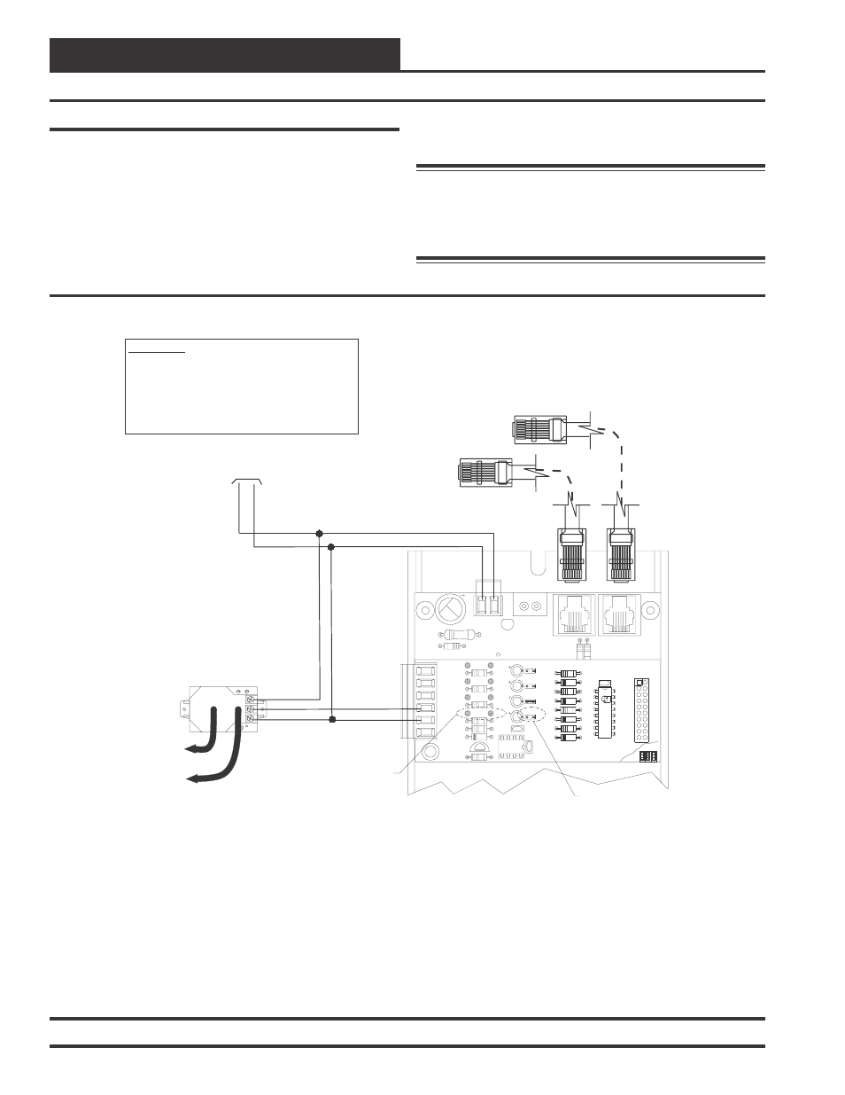
Building Pressure Sensor Wiring
The OE258 Building Pressure Sensor must be wired as shown in the
illustration below for proper operation. There are 3 terminal connec-
tions on the OE258 Building Pressure Sensor. Connect the power side
of the 24 VAC power source to the terminal labeled “+ EXC” . Connect
the GND side of the 24 VAC power source to the terminal labeled “-
COM”. Connect the remaining terminal labeled “OUT” to AIN4 on the
OE354, 4 Analog Output 1 Analog Input Expansion Board terminal
block. See Figure 23 below for detailed wiring. The pullup resistor P4
on the expansion board must be removed and the voltage jumper J04
24
V
A
C
GND
10 VA Minimum Power Required For
Each 2 Slot Expansion Base Board.
20 VA Minimum Power Required For
Each 4 Slot Expansion Base Board
R20
C8
TB2
D3
PWR LD1
24V
AC-IN
GND
GND
TB1
PJ2
+24VDC-OUT
R17
PJ1
R15
Connect To VCM Controller
Connect To Next Expansion Base Board
(When Used)
OE354
-
4
Analog
Input
Board
-
1
Analog
Output
Board
GND
AIN4
EXC
COM
OUT
0-5 VDC Input
HIGH
LOW
-
+
+
+
Tubing To Building
Pressure Sensing Location
Tubing To Atmospheric
Pressure Sensing Location
-
+
JO3
JO4
JO2
JO1
CX2
R10
AOUT1
AIN4
TB1
GND
AIN2
AIN3
AIN1
PU4
U2
D5
Q1
R8
R9
LM358
C5
C1
R7
R6
R5
PU3
C4
C3
C2
PU2
PU1
4 ANALOG IN MOD. I/O BD.
R3
PCF8591P
YS101784
D4
R4
D3
D1
D2
R2
R1
PHILIPS
T L
HA
AN
I D
CX1
U1
P1
Pullup Resistor PU4 Must
Be Removed As Shown
Jumper J04 Must
Be Removed As Shown
OE352 or OE353 Expansion Base Board
OE258
Building Pressure Sensor
WARNING!!
Observe Polarity! All boards must be wired with GND-to-
GND and 24VAC-to-24VAC. Failure to observe polarity will
result in damage to one or more of the boards. Expansion
Boards must be wired in such a way that power to both the
expansion boards and the controller are always powered
together. Loss of power to the expansion board will cause
the controller to become inoperative until power is restored
to the expansion board.
must also be removed as shown in the wiring diagram for the OE258
Building Pressure Sensor to operate correctly.
Warning: It is very important to be certain that all wiring
is correct as shown in the wiring diagram below.
Failure to observe the correct polarity will result
in damage to the HVAC Unit Controller, Building
Pressure Sensor and the Expansion Board.
Figure 23: Building Pressure Sensor Wiring
Input/Output Wiring Details