Vcm controller technical guide 19, Suction pressure transducer – Orion System VCM Controller User Manual
Page 19
VCM Controller
Technical Guide
19
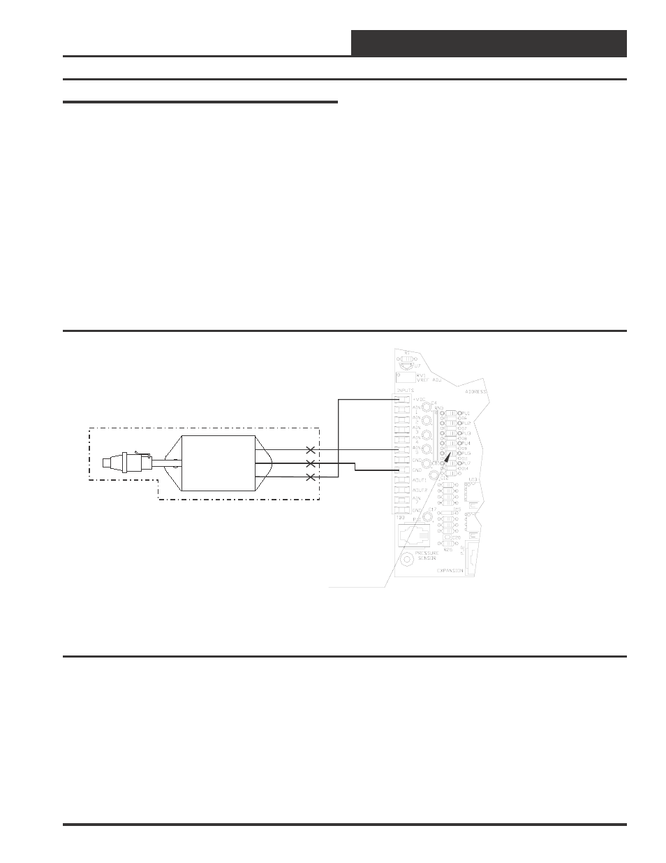
BK
RD
WH
Transducer Cable
With Built-In Signal
Conditioner
OE331-21-VCM
VCM Controller Board
OE275-01-NDC
Suction Pressure
Transducer
(250 PSIG)
With Signal Conditioner
AIN5
GND
+VDC
Pullup Resistor PU5
Must Be Removed
Suction Pressure Transducer
The Suction Pressure Transducer is required for any VCM application
with DX Cooling that requires Dehumidification. It is also required for
any application which utilizes a digital scroll compressor.
The Suction Pressure Transducer is used to measure suction pressure at
the HVAC units DX evaporator coil suction line. This suction line pres-
sure is converted to saturated refrigerant temperature by the VCM con-
troller. This temperature is used by the VCM controller to accurately
control the compressors and reheat cycle components to provide opti-
mum performance from the system during Dehumidification operation.
When used in dehumidification applications on HVAC units without
digital scroll compressors the Suction Pressure Transducer wires to the
VCM controller board as shown in Figure 15. In this application the
Suction Pressure Transducer connects to the VCM board through a cable
with a built-in signal conditioner. The cable is supplied with a 3 pin
Packard mating connector for attachment to the sensor on one end and
has 3 color coded stripped wires on the other end. The stripped wire
ends can be spliced to other wires to extend the wiring length when
required.
For applications that use a Digital Scroll Compressor, the Suction Pres-
sure Transducer wires directly to the Digital Scroll Compressor Con-
troller supplied by the compressor manufacturer. See Figure 16 for
wiring details.
In this application the Suction Pressure Transducer connects to the digital
scroll compressor with a prefabricated cable similar to the one used in
the previous application but without the signal conditioner built in. The
signal conditioning is controlled by the Digital Compressor controller.
This cable also has a 3 pin Packard mating connector for attachment to
the sensor on one end and has 3 color coded stripped wires on the other
end. The stripped wire ends can be spliced to other wires to extend the
wiring when required to connect the Digital Compressor controller.
Figure 15: Suction Pressure Transducer Wiring (Units Without Digital Compressors)