Input/output wiring details, Figure 27: modulating cooling device wiring, Warning – Orion System VCM Controller User Manual
Page 30
Technical Guide
VCM Controller
30
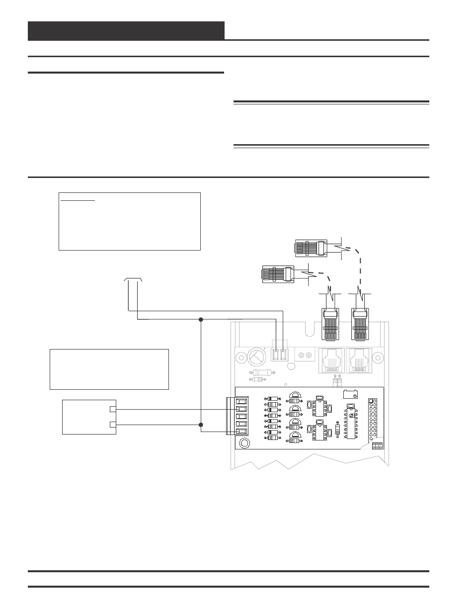
Modulating Cooling Device Wiring
The Modulating Cooling Device signal can be configured for either a
0-10 VDC, 2-10 VDC or 1.5-5.0 VDC output signal. The output signal
can also be configured for either Direct Acting or Reverse Acting op-
eration as required by your application. This signal output would nor-
mally be connected to a Modulating Chilled Water Valve or Digital
Compressor Controller.
See Figure 27 for detailed wiring of the Modulating Cooling Device
when using a Chilled Water Valve. When this output is used with a
Digital Compressor, the Suction Line Pressure Transducer must be wired
24
V
A
C
GND
10 VA Minimum Power Required For
Each 2 Slot Expansion Base Board.
20 VA Minimum Power Required For
Each 4 Slot Expansion Base Board
R20
C8
TB2
D3
PWR LD1
24V
AC-IN
GND
GND
TB1
PJ2
+24VDC-OUT
R17
PJ1
R15
Connect To VCM Controller
Connect To Next Expansion Board
(When Used)
GND
AOUT2
+
Modulating Cooling Device
(By Others)
_
GND
OE355
-
4
Analog
Out
p
ut
Board
OE352 or OE353 Expansion Base Board
WARNING!!
Observe Polarity! All boards must be wired with GND-to-
GND and 24VAC-to-24VAC. Failure to observe polarity will
result in damage to one or more of the boards. Expansion
Boards must be wired in such a way that power to both the
expansion boards and the controller are always powered
together. Loss of power to the expansion board will cause
the controller to become inoperative until power is restored
to the expansion board.
0-10 VDC, 2-10 VDC or 1.5-5.0 VDC
(Configurable)
The Modulating Cooling Device Used Must Be Designed
To Accept Either A 0-10 VDC, 2-10 VDC Or 1.5-5.0 VDC
Input. The AOUT1 Output Voltage Is User Configurable
For These Voltages. The Cooling Device Used Can Be A
Modulating Chilled Water Valve or A Digital Scroll
Compressor. If Using A Digital Scroll Compressor
Please See Digital Scroll Detailed
Information In
This Manual.
Wiring
GND
AOUT1
YS101786
4 AOUT MOD. I/O BD.
CX1
U1
Q1
LM358
R2
U2
R9
D1
R6
D2
R7
D4
D3
R8
TB1
CX2
C3
C1
P1
RV
1
R1
C4
U3
C2
LM358
CX3
AOUT2
AOUT3
AOUT4
Q2
R3
Q4
Q3
R4
R5
to the Digital Compressor Controller instead of the VCM board and the
Modulating Cooling Output signal must be configured for a 1.5 to 5.0
VDC output signal. For Digital Compressor wiring details
see Figure 16.
Warning: It is very important to be certain that all wiring
is correct as shown in the wiring diagram
below. Failure to observe the correct polarity could
result in damage to the Modulating Cooling Device.
Figure 27: Modulating Cooling Device Wiring
Input/Output Wiring Details