Vcm controller technical guide 17, Outdoor air temperature sensor – Orion System VCM Controller User Manual
Page 17
VCM Controller
Technical Guide
17
GND
INPUTS
GND
AOUT1
AOUT2
GND
+VDC
AIN1
AIN2
AIN3
AIN4
AIN5
AIN7
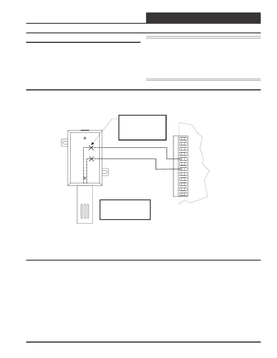
OE250
Outdoor Air
Temperature Sensor
Make Splice Connections
Inside Sensor Enclosure
As Shown. Seal All
Conduit Fittings With
Silicone Sealant.
Mount Sensor Outdoors
In Shaded Protected
Area & In Upright
Position As Shown
OE331-21-VCM
VCM Controller Board
Outdoor Air Temperature Sensor
The Outdoor Air Sensor must be wired as shown in the illustration be-
low for proper operation of the VCM controller. The Outdoor Air Tem-
perature Sensor is a 10K Type III thermistor sensor. The sensor should
be mounted in the upright position as shown, in an area that is protected
from the elements and direct sunlight. Be sure to make the wiring splices
inside of the Outdoor Air Temperature Sensor weather-tight enclosure.
See Figure 13 for detailed wiring.
Figure 13: Outdoor Air Temperature Sensor Wiring
Caution:
Be sure to mount the Outdoor Air Sensor in an
area that is not exposed to direct sunlight. The
shaded area under the HVAC unit rain hood is
normally a good location. Unused conduit
opening(s) must have closure plugs installed
and must be coated with sealing compound to
provide a rain tight seal. Water can damage
the sensor.