Front panel interface, Non-lcd option, Leds – Verilink PRISM 3111 (34-00242) Product Manual User Manual
Page 29: Net backup test alarm power, Ront, Anel, Nterface
3
F
RONT
P
ANEL
I
NTERFACE
Depending on your ordering options, the PRISM 3111/3112 front panel comes
with or without an LCD screen option and option specific control buttons.
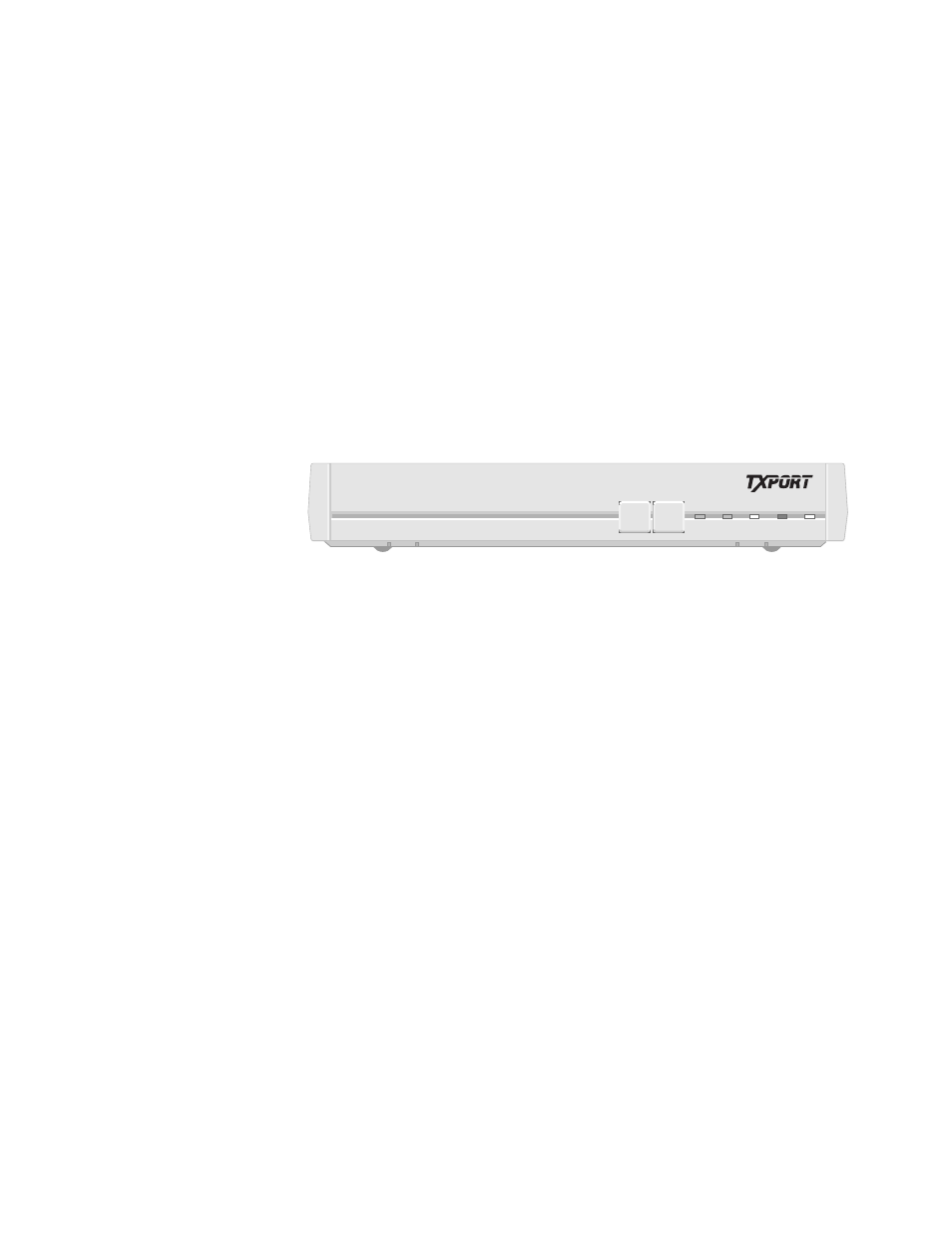
Non-LCD Option
The non-LCD front panel interface option (Figure 3-1) allows you to troubleshoot
the unit using loop tests without having to connect a terminal to the unit. The tests
can be run using the two front panel buttons. The five LED indicators allow you to
see the unit’s status.
Figure 3-1 PRISM 3111/3112 Front Panel (non-LCD option)
LEDs
Five front panel LEDs allow a visual identification of the test results and alarms.
These LEDs are: NET, BACKUP, TEST, ALARM, and POWER.
NET
This LED illuminates green when the unit is in frame sync. It illuminates amber
when the unit receives a yellow alarm from the far end. It illuminates red when the
unit is out of frame and/or loss of signal.
BACKUP
Amber LED blinks when dialing, connecting, or disconnecting. It illuminates when
active.
TEST
This LED flashes green when the unit is transmitting loop code. It is green
continuously when BERT is on with no errors, when the unit is in a loop
condition, or when the unit is in clear test. It is red when the BERT is on and is
receiving errors.
ALARM
Red LED illuminates when the unit is in an active alarm condition.
POWER
Green LED illuminates when power is applied to the unit.
TEST
LOOP
BACKUP
NET
TEST ALARM POWER
PRISM 3111
®