Snmp configuration, Snmp sets trap ip address – Verilink PRISM 3111 (34-00242) Product Manual User Manual
Page 77
Configuration
69
SNMP Configuration
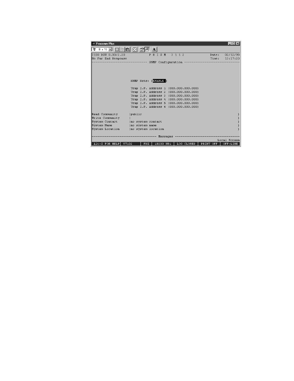
The SNMP Configuration screen (Figure 4-14) allows for the entry of those
parameters required for proper operation with an SNMP- based network manager.
Figure 4-14 SNMP Configuration Screen
The 3111/3112 supports alarm reporting by SNMP traps via the LAN or SLIP
interface. If the unit’s IP Connection is LAN or Direct SLIP, it expects an IP
connection to always be present and outputs its trap messages immediately. If the
IP Connection is Dial SLIP, the unit dials out from the modem connected to the
SLIP port using the number programmed in the Management Ports screen and
outputs trap messages upon connection.
The PRISM 3111/3112 has an embedded SNMP agent supporting MIB-II and the
DS1/E1 MIB. The SET command is supported and has the functionality described
below. The 3111/3112 also supports a single telnet session.
SNMP Sets
This field enables or disables the set command responses for SNMP. Refer to
Appendix A, SNMP Agent, for detailed information on these responses.
TRAP IP Address
These six rows require numeric entries. Each row contains four octets. Each of
these numbers can range from 0 to 255.
These fields accept the IP address of a network device to which alarm reporting
traps are to be sent. The unit detects and reports alarms and provides several
options for reporting them, one of which is SNMP traps. When an alarm occurs,
the unit sends a trap message to up to six destinations on the user’s network. The
trap message is formatted per RFC 1157.
Up to six trap IP addresses can be assigned to report via SNMP. The unit will
report each alarm by transmitting an SNMP trap to each trap IP address.