Signalling channel allocation signalling enabled, Alarm configuration, Errored seconds – Verilink PRISM 3111 (34-00242) Product Manual User Manual
Page 69
Configuration
61
Signalling
Allows you to select Clear Channel or Robbed Bit signalling for each DS0. Each
DS0 is set to the Clear Channel (Disable) mode. This setting should not be
changed for raw data channels. However, channels using Robbed Bit signalling
(Enabled) must be specified for proper handling of the signalling bits. T1 DTE
channels must be set to THRU to enable signalling.
Channel Allocation
This display-only field indicates the network channel assignments with Channel 1
on the left and Channel 24 on the right. Channels assigned to a port are identified
with a port number (1 or 2). Non-assigned idle channels are marked with a dash
(-). Remote communication channels are marked with an R. T1 DTE channels are
marked with a D.
Signalling Enabled
An X in this line indicates that signalling is enabled for that channel.
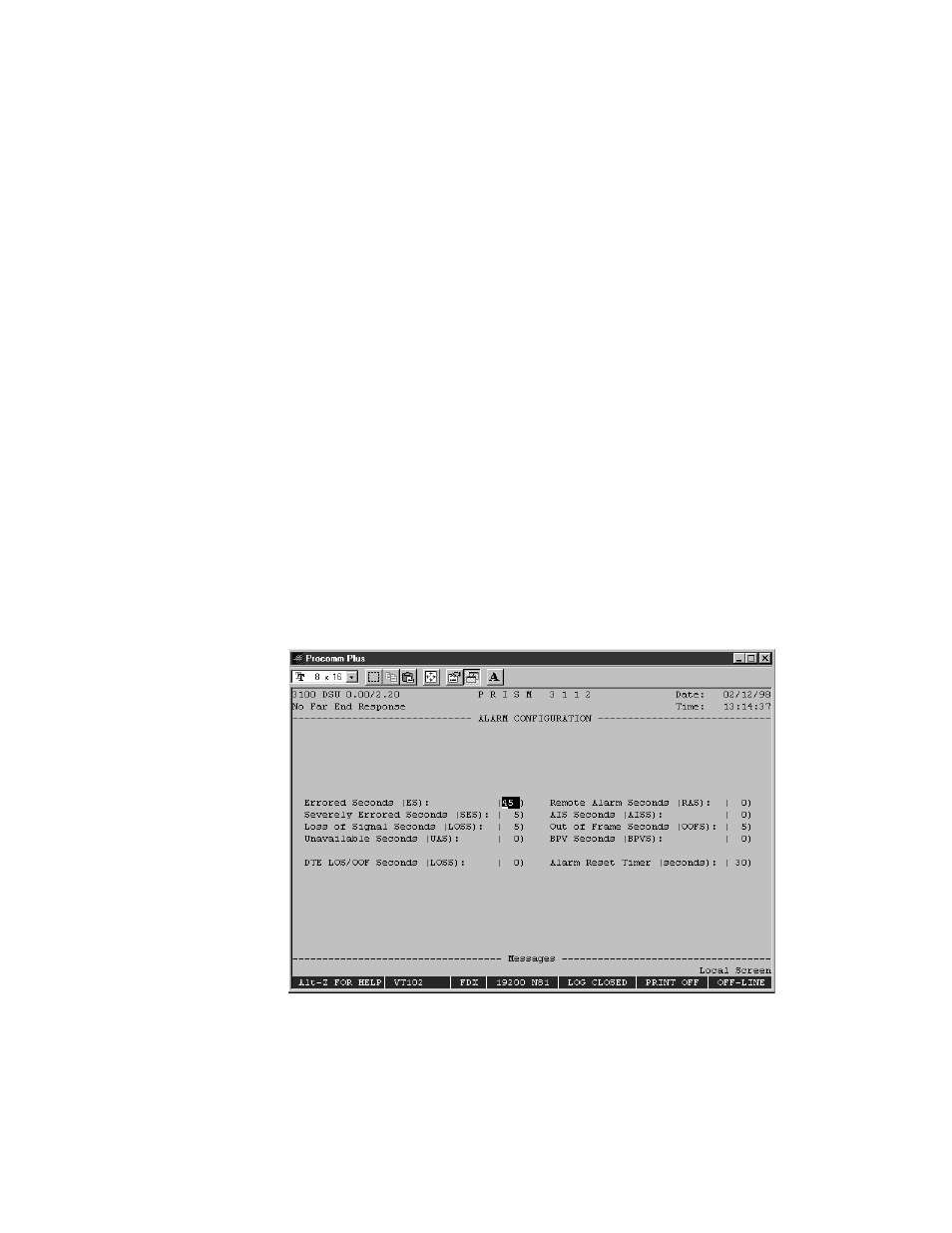
Alarm Configuration
The Alarm Configuration screen (Figure 4-10) allows you to review and set alarm
related thresholds for the selected element. These thresholds are the minimum
acceptable performance levels. To modify the parameters, highlight the desired
statistic, type in the new value (any number from 0 to 900) and press <enter>. If
this value is later surpassed, an alarm indication will appear. A field set to (0) will
cause the element not to alarm on that statistic.
Alarm Parameters are monitored using the AT&T 54016 performance monitoring
status.
Figure 4-10 Alarm Configuration Screen
Errored Seconds
A one second period in which at least one logic error occurred.
✍