Verilink PRISM 3111 (34-00242) Product Manual User Manual
Page 71
Configuration
63
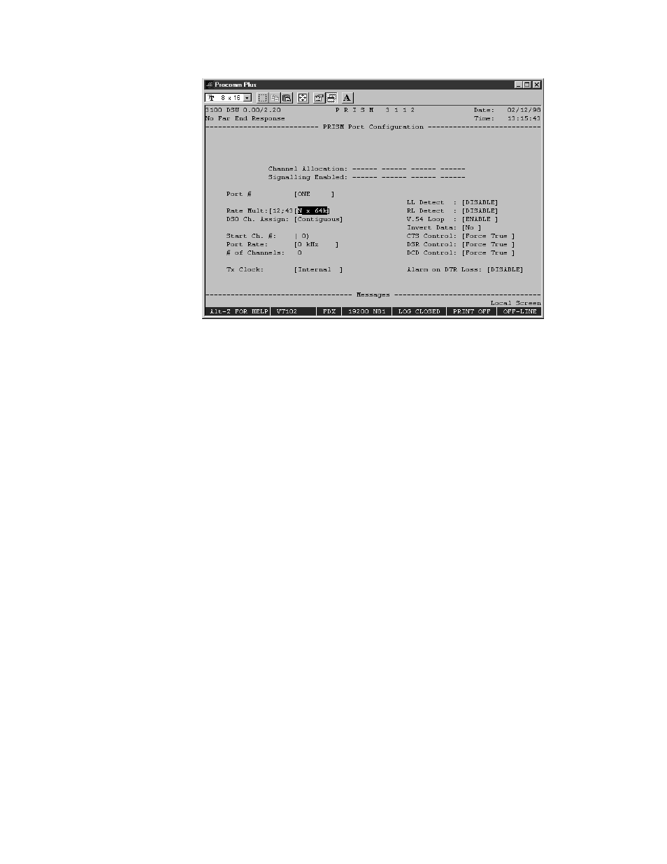
Figure 4-11 Port Configuration Screen
Channel Allocation
This display-only field indicates the network channel assignments with Channel 1
on the left and Channel 24 on the right. Channels assigned to a port are identified
with a port number (1 or 2). Non-assigned idle channels are marked with a dash
(-). Remote communication channels are marked with an ‘R’. When channels are
assigned to a port in the ALTERNATE assignment mode, each data channel is
followed by an idle channel that is not assignable for other ports and is marked
with an ‘X’. T1 DTE channels are shown with a ‘D’.
Signalling Enabled
An X in this line indicates that signalling is enabled for that channel.
Port #
Selects the port to be configured, such as One or Two.
Rate Multiplier
The unit can operate at any data rate that is a multiple of 56 or 64 kbps. When
N x64K is selected, the ones density requirements of the T1 network line must be
ensured. When Nx 56K is selected, the unit maintains ones density for the selected
DS0 channel.
DS0 Channel Assignment
Selects whether the DTE channel assignment will be made as a Contiguous group
or as Alternate channels. Selecting Alternate channel mode assigns an idle channel
following each data channel. For example, data carried on channels 1, 3, 5 and 7.
Channels 2, 4, 6 and 8 are idle (the idle setting is binary code 01111111). The
advantage of alternate channel assignment is that T1 ones density requirements are