Buttons, Test loop, Lcd option – Verilink PRISM 3111 (34-00242) Product Manual User Manual
Page 30: Leds
22
C
HAPTER
3: F
RONT
P
ANEL
I
NTERFACE
Buttons
Two front panel buttons allow you to send loop tests.
TEST
When this button is pushed once, the unit transmits five seconds of in-band loop
code out to the network either LLB or V.54 depending on the setting of
configuration Switch S2 -7 (page 18). If S2-7 is set to V.54, this button performs a
test on Data Port 1 only. The indicator blinks green during transmission of the
loop code.
If configuration Switch S2 -8 (page 18) is set to Clear Loop, the unit goes into a
test mode where it will not generate alarms.
If Switch S2 -8 is set to BERT, the test pattern last selected in the terminal
interface is transmitted toward the network. The received pattern is compared and
if the pattern is received error free, the TEST indicator remains green. If pattern
errors are detected, the TEST indicator turns red for one second for each errored
second. Therefore, if five errored seconds are received, the indicator will remain
red for five seconds.
If the TEST button is pushed again, the unit transmits five seconds of in-band loop
down code and returns to normal operating mode. The TEST indicator is then
turned off.
LOOP
When this button is pressed once, the unit activates a line loopback, looping the
network receive data back to the network (Net LLB). The TEST indicator is
illuminated while the unit is in loop. If pressed again, the unit clears the loop and
turns off the LOOP indicator.
For additional information concerning test and loop options, refer to page 28.
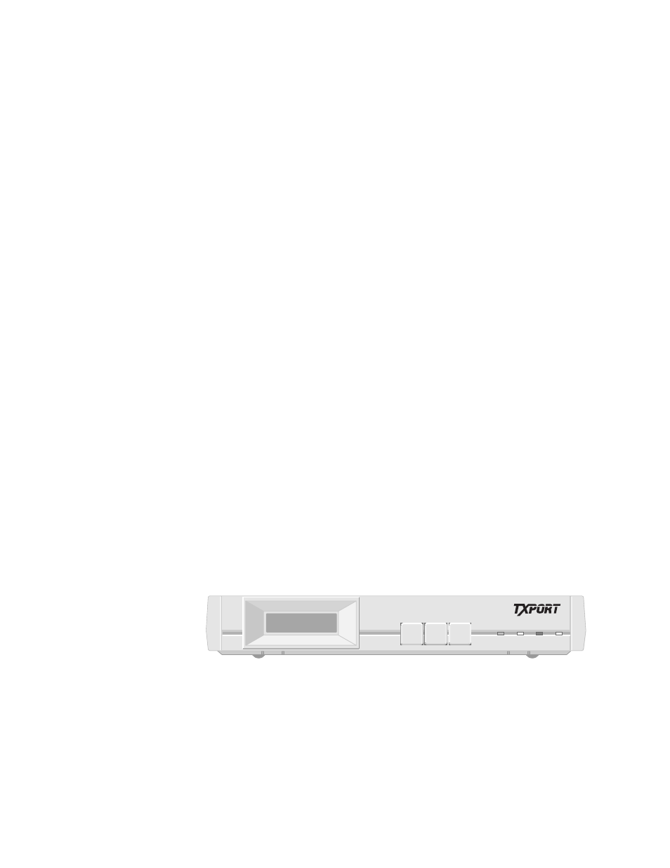
LCD Option
The LCD front panel interface option (Figure 3-2) allows you to configure
network, port, and SNMP parameters and troubleshoot the unit using loop tests
and BERTs without having to physically connect a terminal to the unit. The
interface screen can be manipulated using the three front panel buttons. The
interface screen and the four LED indicators allow you to see the unit’s status.
Figure 3-2 PRISM 3111/3112 Front Panel (LCD option)
LEDs
Four front panel LEDs allow a visual identification of the test results and alarms.
These LEDs are: BACKUP, TEST, ALARM and POWER.
✍
SCROLL
EXIT
SELECT
BACKUP TEST ALARM POWER
PRISM 3111
®