Management ports, Element id – Verilink PRISM 3111 (34-00242) Product Manual User Manual
Page 78
70
C
HAPTER
4: T
ERMINAL
I
NTERFACE
T1 network problems often cause more than one alarm type. In these cases,
multiple trap messages are generated, each with a different specific trap type.
Read Community
This display accepts a character string (up to 58 characters) identifying the group
authorized to perform read operations. The default setting is public.
Write Community
This display accepts a character string (up to 58 characters) identifying the group
authorized to perform write operations. The default setting is a null string (‘ ’).
System Contact
This display accepts a character string (up to 58 characters) identifying the person
responsible for a network device. The default setting is no system contact.
System Name
This display accepts a character string (up to 58 characters) identifying the
functionality of the network device. The default setting is no system name.
System Location
This display accepts a character string (up to 58 characters) identifying the
physical location of network device. The default setting is no system location.
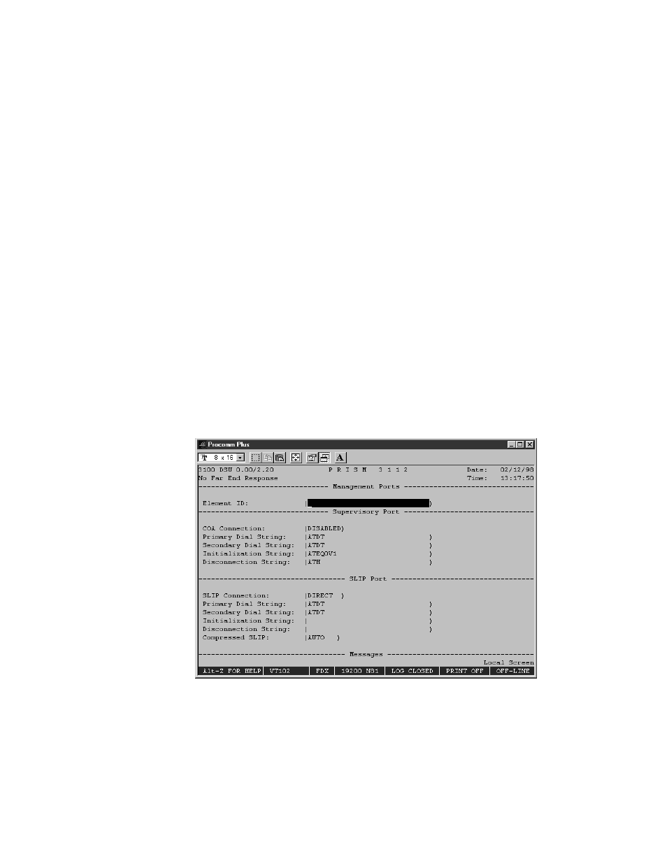
Management Ports
The Management Ports screen (Figure 4-15) sets the following parameters for the
Call On Alarm (COA) connection on both the SUPV and SLIP ports.
Figure 4-15 Management Ports Screen
Element ID
This field allows the entry of an ASCII string (29 characters in length) which
identifies the unit to the device receiving the alarm notification messages.