Grass Valley DD35 Family v.3.1.5 User Manual
Page 327
3. Menu Operation
DD35 Production Switcher
3 – 175
Operating Instructions – Rev. 16 / 10.2001
3.16.2.3 Timing Adjustment DD35
When source signals are fed into the switcher, it must be ensured that the time dif-
ference between the sources is not outside the operating range of the internal
switcher autophasers (DD35 = 22
µ
s). The output signals of the sources must cor-
respond to the timing customary in operation. For instance, no EE picture in a VTR,
PB-Ref on CCVS etc.
The switcher’s Genlock Phase can be adjusted to the fed reference signal in the
range of –15 line to +15 lines.
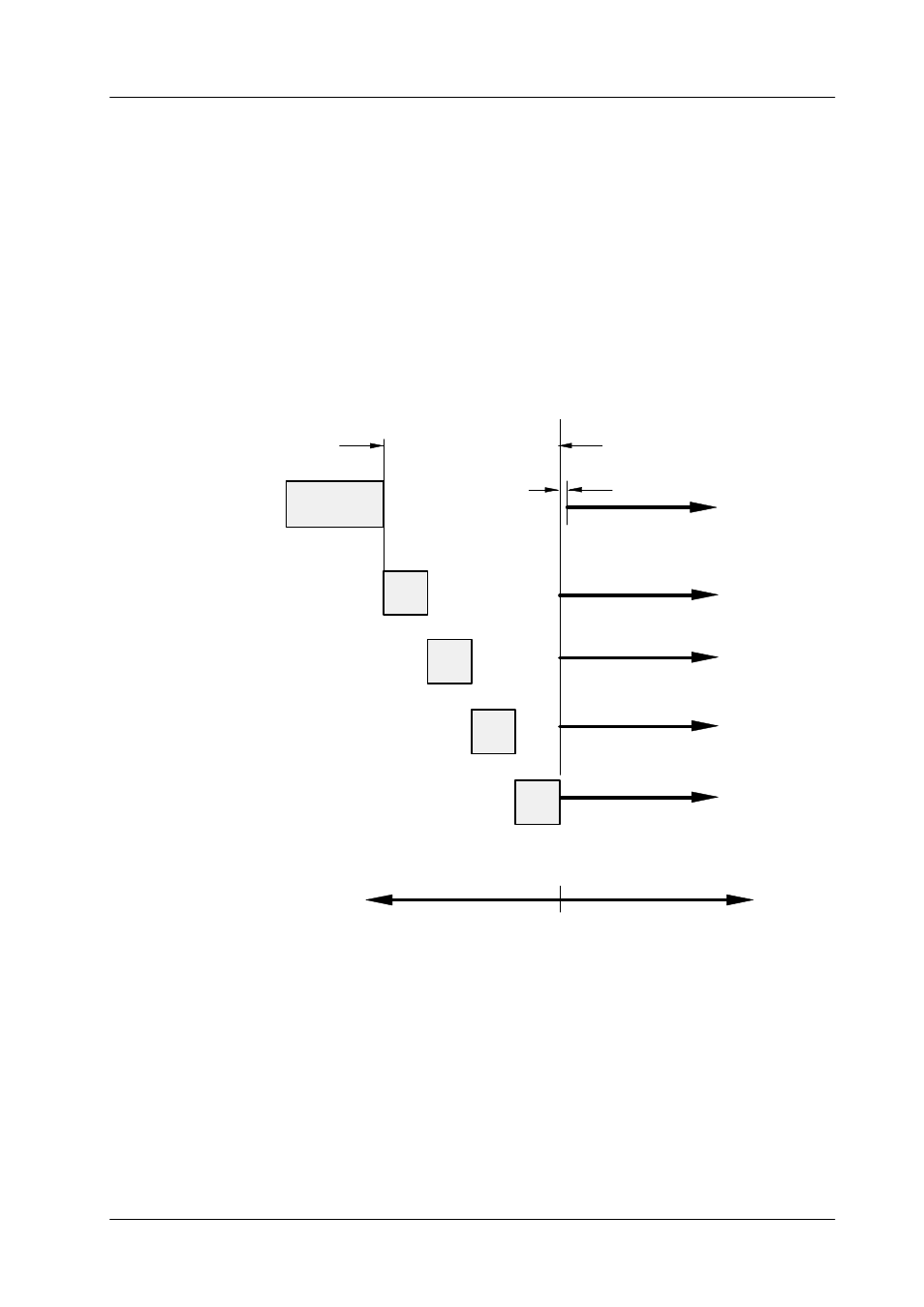
Autophasing
ME1
approx 22 us
approx 10 us
Min delay
approx 0.8 us
Aux outputs
ME3 output, PVW
Timing reference diagram for DD35-4
ME2
approx 10 us
ME3
approx 10 us
ME2 output, PVW
Main outputs, PVW
approx 41 us
Total timing position of DD35 in respect to reference blackburst::
approx minus 15 lines
approx plus 15 lines
PP
approx 10 us
ME1 outputs, PVW
range inputs
Refer to the Installation Manual for detailed information for DD35-2
and DD35-3 switchers.