Installing the option – Yaskawa SI-EN3D User Manual
Page 13
u
Installing the Option
Remove the front covers of the drive before installing the option. Refer to the drive Quick Start Guide for directions on
removing the front covers. Cover removal varies depending on drive size. This option can only be inserted into the CN5-A
connector located on the drive control board.
DANGER! DANGER! Electrical Shock Hazard. Do not connect or disconnect wiring while the power is on. Failure to comply could result in
death or serious injury. Before installing the option, disconnect all power to the drive and wait at least the amount of time specified on the
drive front cover safety label. After all indicators are off, measure the DC bus voltage to confirm safe level, and check for unsafe voltages
before servicing. The internal capacitor remains charged after the power supply is turned off.
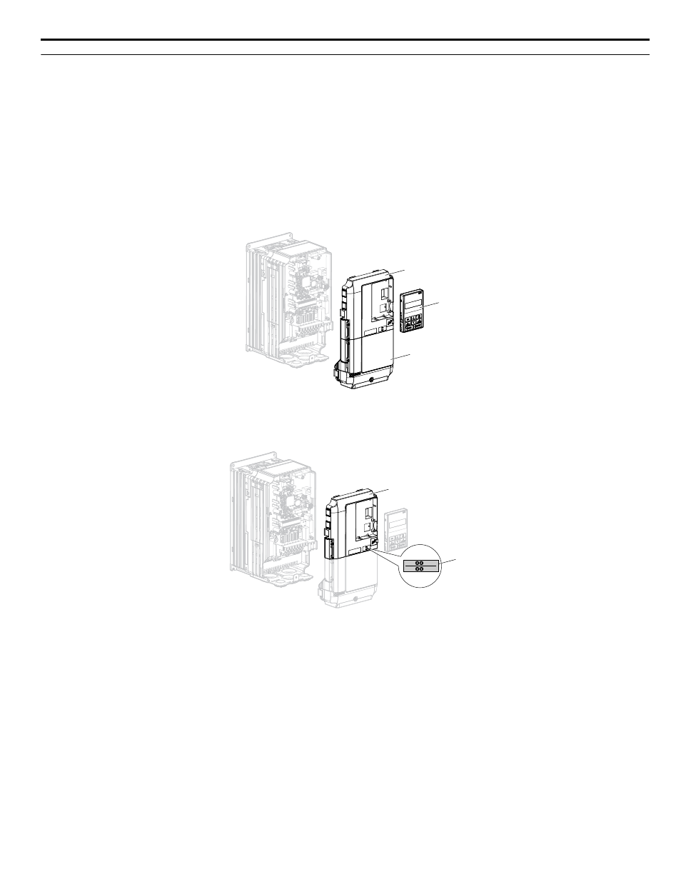
1.
Shut off power to the drive, wait the appropriate amount of time for voltage to dissipate, then remove the digital operator
(B) and front covers (A, D). Front cover removal varies by model.
NOTICE: Damage to Equipment. Observe proper electrostatic discharge procedures (ESD) when handling the option, drive, and
circuit boards. Failure to comply may result in ESD damage to circuitry.
A
B
D
Figure 3 Remove the Front Covers and Digital Operator
2.
With the front covers and digital operator removed, apply the LED label (C) in the appropriate position on the drive
top front cover (A).
A
C
NS
MS
Figure 4 Apply the LED Label
3.
Make sure the screws on the left and right sides of the option terminal block (J) are tightened with a tightening torque
of 0.5 to 0.6 Nm (4.4 to 5.3 in lbs), then insert the option (B) into the CN5-A connector (L) located on the drive and
fasten it using one of the included screws (H).
5 Installation Procedure
YASKAWA SIEP YAICOM 16A 1000-Series Option Dual-Port EtherNet/IP SI-EN3D Technical Manual
13